
Calf, ankle, foot, or leg rest for cane and cane with device attached

a technology of canes and legs, applied in the direction of suspension devices, machine supports, furniture parts, etc., can solve the problems of not being very portable and often creating great discomfort in using a chair for this purpos

Active Publication Date: 2009-06-18
MONTANTI JOHN A
View PDF22 Cites 3 Cited by
  • Summary
  • Abstract
  • Description
  • Claims
  • Application Information

AI Technical Summary

Benefits of technology

[0003]The invention disclosed herein is a calf, ankle, foot, or leg rest device which can be snapped onto a cane for use or snapped off when only the use of the cane is desired. The invention also encompasses the combination cane and rest device. The rest device is a J-shaped soft padded bracket that is rigidly attached to the cane. The height of the bracket along the cane is adjustable to provide comfort and ease of use. The cane may be positioned at a convenient horizontal distance from the user as desired. In this way, the user may rest his or her calf, ankle, or heel on the rest device. Once the rest device is engaged by the user's leg, the cane is perfectly balanced on the ground. A user can comfortably keep his leg in a horizontal position for hours.
[0005]The first improvement is a J-shaped resting device wherein the bottom part of the “J” is hinged to the vertical stem of the “J.” Ordinarily, the bottom part of the “J” protrudes horizontally. However, the improved resting device allows the bottom part to be moved into a vertical position to make using the cane more convenient when the user is walking.
[0011]The seventh improvement is the use of two identical resting devices mounted opposite to each other on the cane. This creates a cane whereby a user may elevate both legs to a horizontal position.

Problems solved by technology

Using a chair for this purpose often creates great discomfort.
A hassock is more comfortable than a chair, but it is not very portable.

Method used


Image

  • Calf, ankle, foot, or leg rest for cane and cane with device attached
  • Calf, ankle, foot, or leg rest for cane and cane with device attached
  • Calf, ankle, foot, or leg rest for cane and cane with device attached

Examples


Embodiment Construction

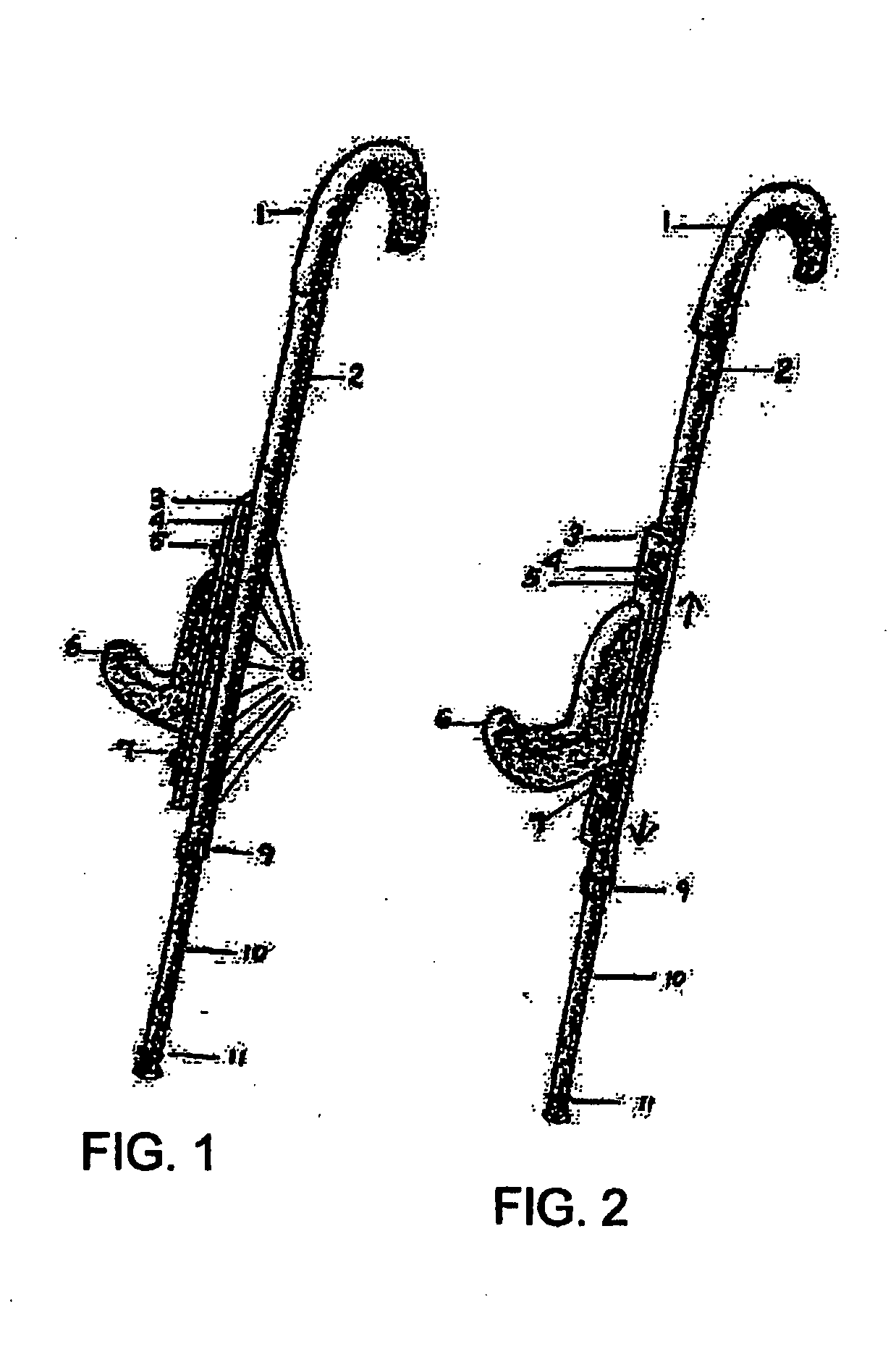
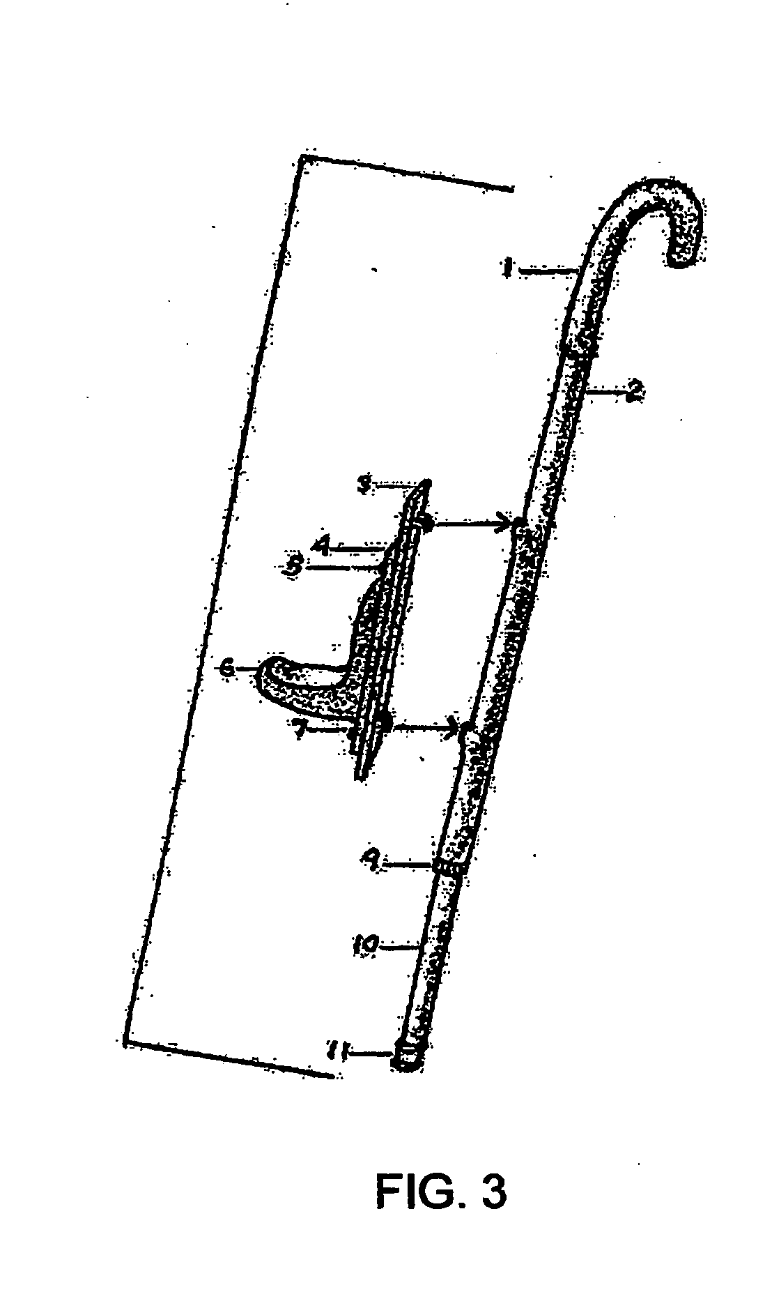
[0065]The invention disclosed herein is a calf, ankle, foot, or leg rest device (hereinafter, Resting Device) and a cane modified by having the Resting Device movably mounted thereon. FIG. 1 is an isometric view of the cane showing the Resting Device positioned using mounting holes located on the opposite side of the cane. The mounting holes in the rear of the cane are visible. FIG. 2 is an isometric view of the cane rotated 90° counter-clockwise from FIG. 1 about the longitudinal axis of the cane. Referring to FIGS. 1 and 2, the basic cane comprises a hand grip, 1; an upper cane section, 2; cane height adjustment holes, 8, through which a spring driven snap button protrudes thereby locking in the desired height; a lower adjustable extension section, 10, containing one spring driven snap button to lock in the desired cane height by snapping the button outward through one of the holes in the upper cane section; a knurled cam nut, 9, which is tightened once the desired height is reach...


PUM


Abstract

A calf, ankle, foot, or leg rest device which can be snapped onto a cane for use or snapped off when only the use of the cane is desired. The invention also encompasses the combination cane and rest device. Many people who either have a permanent leg, knee, or foot disability or are recovering from a leg, knee, or foot operation are required to keep their leg in a horizontal position while seated. The rest device is a J-shaped soft padded bracket that is rigidly attached to the cane. The height of the bracket along the cane is adjustable to provide comfort and ease of use. The cane may be positioned at a convenient horizontal distance from the user as desired. In this way, the user may rest his or her calf, ankle, or heel on the rest device. Once the rest device is engaged by the user's leg, the cane is perfectly balanced on the ground. A user can comfortably keep his leg in a horizontal position for hours.

Description

CROSS REFERENCE TO RELATED APPLICATIONS[0001]The Present Non-Provisional Patent Application is being filed pursuant to 35 U.S.C. §371 as a US National Stage Patent Application deriving from PCT International Application No. PCT / US 06 / 24035 filed on Jun. 22, 2006 under the Patent Cooperation Treaty which is the non-provisional counterpart to U.S. Provisional Application Ser. No. 60 / 597,177 filed on Nov. 17, 2005 and U.S. Provisional Application Ser. No. 60 / 743,077 filed on Dec. 25, 2005. The Present National Stage Application PCT Application claims the benefit of and priority to the PCT Application ant to both US provisional applications cited herein.BACKGROUND OF THE INVENTION[0002]Many people who either have a permanent leg, knee, or foot disability or are recovering from a leg, knee, or foot operation are required to keep their leg in a horizontal position while seated. These people usually rest a leg on a chair or a hassock. Using a chair for this purpose often creates great disc...

Claims


Application Information

Patent Timeline
Patent Type & Authority Applications(United States)
IPC IPC(8): A45B3/00A47B96/06A47B96/07
CPCA45B1/00A61H2003/005A61H3/00
Inventor MONTANTI, JOHN
Owner MONTANTI JOHN A
Learn More