
Push-button control device

Inactive Publication Date: 2009-06-11
TISSOT SA
View PDF5 Cites 13 Cited by
  • Summary
  • Abstract
  • Description
  • Claims
  • Application Information

AI Technical Summary

Benefits of technology

[0011]It is an object of the present invention to overcome the aforementioned drawbacks, in addition to others, by providing a push-button control device of simple and economical construction, which has improved water-resistant properties even in deep dive conditions.

Problems solved by technology

It has been observed that the water resistance of this type of push-button is not entirely satisfactory for dive watches.
Indeed, during deep dives, the O-ring gaskets can be subjected to pressure that is so high, typically of the order of several dozen atmosphere, that they can no longer ensure the required level of water resistance.
However, if such a gasket is inserted, or if several gaskets are inserted in the type of construction described above, the friction between the gaskets and the guide tube greatly increases and there is a risk that the tube will not return to its rest position because of this friction once the pressure on the push-button head has ceased.
This construction, however, still has drawbacks.
First of all, it cannot be used with conventional push-buttons, i.e. push-buttons with a head sliding around a smooth bent tube, since the tube has to be adapted in order for the ring to be secured thereto.
This solution is not, therefore, economical.
Moreover, given the shape of the peripheral edge of the membrane, if the ring is tightened too vigorously onto the tube, this may buckle the edge and thus compromise the desired water resistance.
This Patent has the drawback of concealing the push-buttons and requiring the entire watchcase to be dismantled in the event that the ring needs to be changed, which thus involves consulting a watchmaker.
Moreover, the entire ring has to be changed, which makes replacement uneconomical.

Method used


Image

  • Push-button control device
  • Push-button control device
  • Push-button control device

Examples


Embodiment Construction

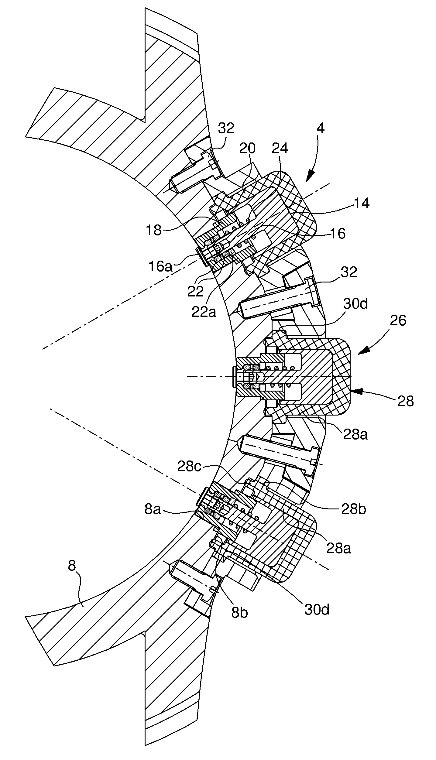
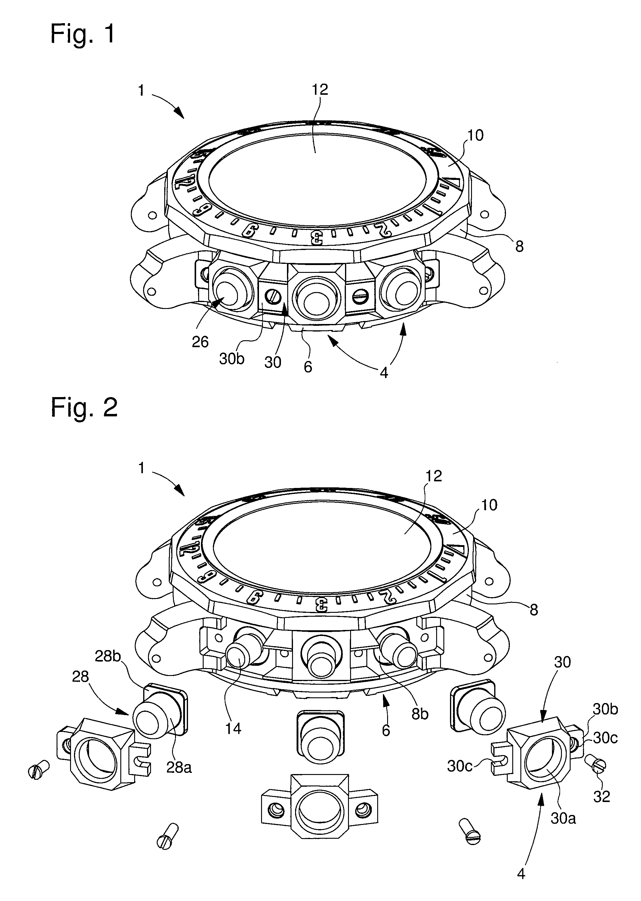
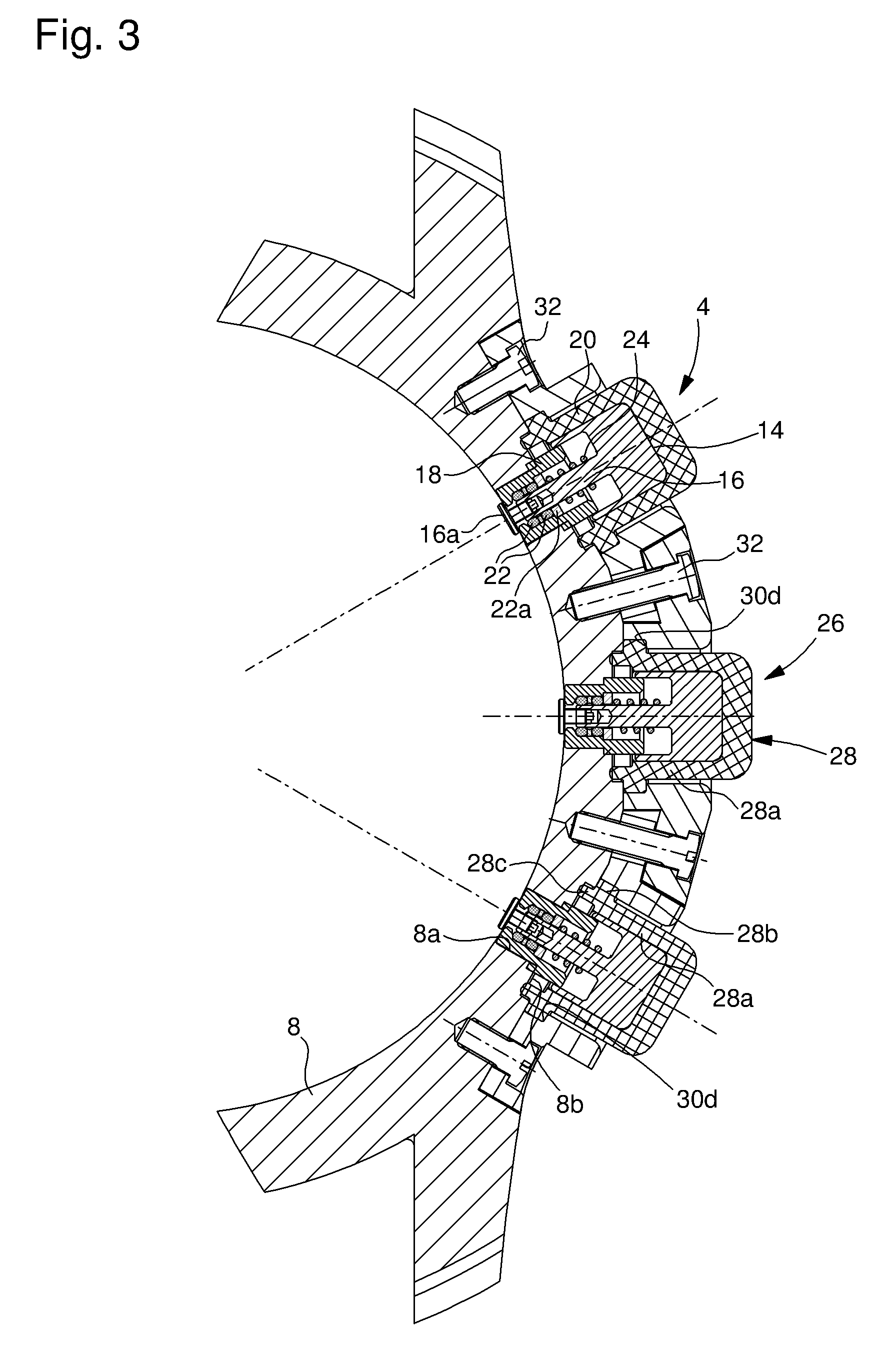
[0019]FIGS. 1 and 2 show a timepiece, in this case a wristwatch, designated by the general reference 1, whose case is fitted with a plurality of push-button control devices 4. In this example, there are three push-button devices.

[0020]The case is comprised, in a conventional manner, of a back cover 6, a middle part 8 and a bezel 10, closed by a crystal 12. The case thus defines a housing for a timepiece movement (not shown), which includes various mechanisms associated with functions that can be activated respectively by the push-button control devices 4.

[0021]Each push-button control device 4 includes a push-button head 14 secured to a push-button stem 16, which passes through a guide tube 18, mounted on middle part 8 and projecting from said middle part. Typically, tube 18 has a shoulder and is directly driven into a bore 8a in middle part 8. Alternatively, tube 18 may also be screwed onto the middle part with the insertion of a sealing gasket between the shoulder surface of the t...


PUM


Abstract

The present invention concerns a push-button control device for a timepiece, including a push-button head secured to a push-button stem that is fixed to a timepiece case, said stem being able to move axially between at least a rest position and an active position, against a return member, to control at least one function of said timepiece, and water-resistant sealing means, said device being characterized in that the water-resistant sealing means include a cap made of flexible, water-resistant material which covers the push-button head and which is secured to the timepiece case.

Description

[0001]This application claims priority from European Patent Application No. 07121716.0, filed Nov. 28, 2007, the entire disclosure of which is incorporated herein by reference.FIELD OF THE INVENTION[0002]The present invention relates to the field of watchmaking. It concerns more specifically a water resistant push-button control device for a watch.BACKGROUND OF THE INVENTION[0003]Push-button devices control various functions in timepieces. Typically, the start, stop and reset functions of a chronograph watch are controlled by these devices, which are mounted on the middle part of the watchcase.[0004]Conventionally, push-button control devices include a push-button tube that is fixed to the middle part of the watch, in an aperture therein. A push-button stem, associated with a push-button head, is arranged inside the tube so that it can slide axially therein, between a rest position and an active position, against the force of a return spring. The surface of the push-button head that...

Claims


Application Information

Patent Timeline
IPC IPC(8): G04B37/12
CPCG04B37/106G04B27/001
Inventor CLERC, NICOLASAPOTHELOZ, DAVID
Owner TISSOT SA
Learn More