Liquid Crystal Display and Television Receiver
a liquid crystal display and television receiver technology, applied in static indicating devices, instruments, non-linear optics, etc., can solve problems such as poor reliability, poor response properties, and interference occurring between liquid crystal panels, and achieve the effects of reducing interference, reducing interference, and reducing moire pattern occurren
- Summary
- Abstract
- Description
- Claims
- Application Information
AI Technical Summary
Benefits of technology
Problems solved by technology
Method used
Image

Examples
embodiment 1
[0268]The present embodiment will describe lowering moire pattern occurrences by providing a light diffusion layer in the liquid crystal display 100.
[0269]First will be described the results of experiments on the relationship between moire pattern occurrences and haze in a light diffusion layer and also on the crispness of a black display under those conditions.
[0270]FIG. 17 shows the results of the experiments (result 1 to result 3). FIGS. 18, 19 show panel structures (experimental systems) used in the experiments. Two test panel models were used: (1) a 37-inch WXGA-format panel (Resolution=1366×RGB×768; Pixel dimensions (width×height)=200 μm×600 μm) and (2) a 37-inch full HDTV (“Full HD”; Resolution=1920×RGB×1080; Pixel dimensions (width×height)=142.25 μm×426.75 μm). In each version, a color panel was disposed on the front side, and a black and white panel was disposed on the back side. Both were attached to the backlight. The B&W panel was identical to the color panel, except tha...
embodiment 2
[0289]In the present embodiment, at least one of the inner transparent substrates is rendered thinner than the outer transparent substrates so as to restrain moire pattern occurrences in the liquid crystal display containing a combination of liquid crystal panels.
[0290]FIG. 24 shows the same liquid crystal display 100 as the one in FIG. 3 with optical paths added.
[0291]The liquid crystal display 100 in FIG. 24 has two possible optical paths depending on viewing angle: optical path (1) for the viewer in the front direction and optical path (2) for the viewer at an oblique angle. The light traveling along optical path (1) appears normal to the viewer. Meanwhile, the light traveling along optical path (2) may appear off-color or produce a non-uniform image depending on the angle and the type of image because the light passes an adjacent pixel in the second panel. This is the moire attributable to parallax.
[0292]In the example shown in FIG. 25, the inner substrates (2), (3) are thinner ...
embodiment 3
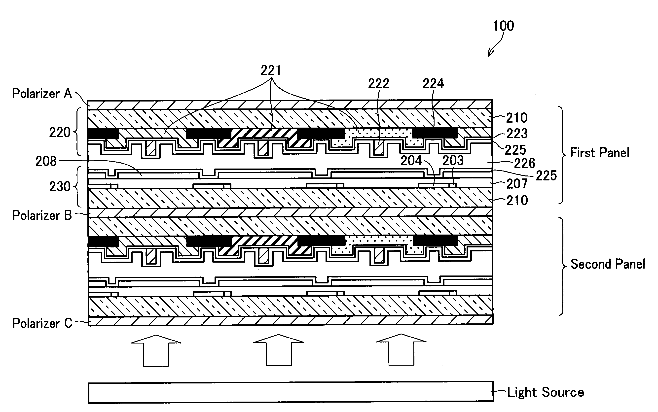
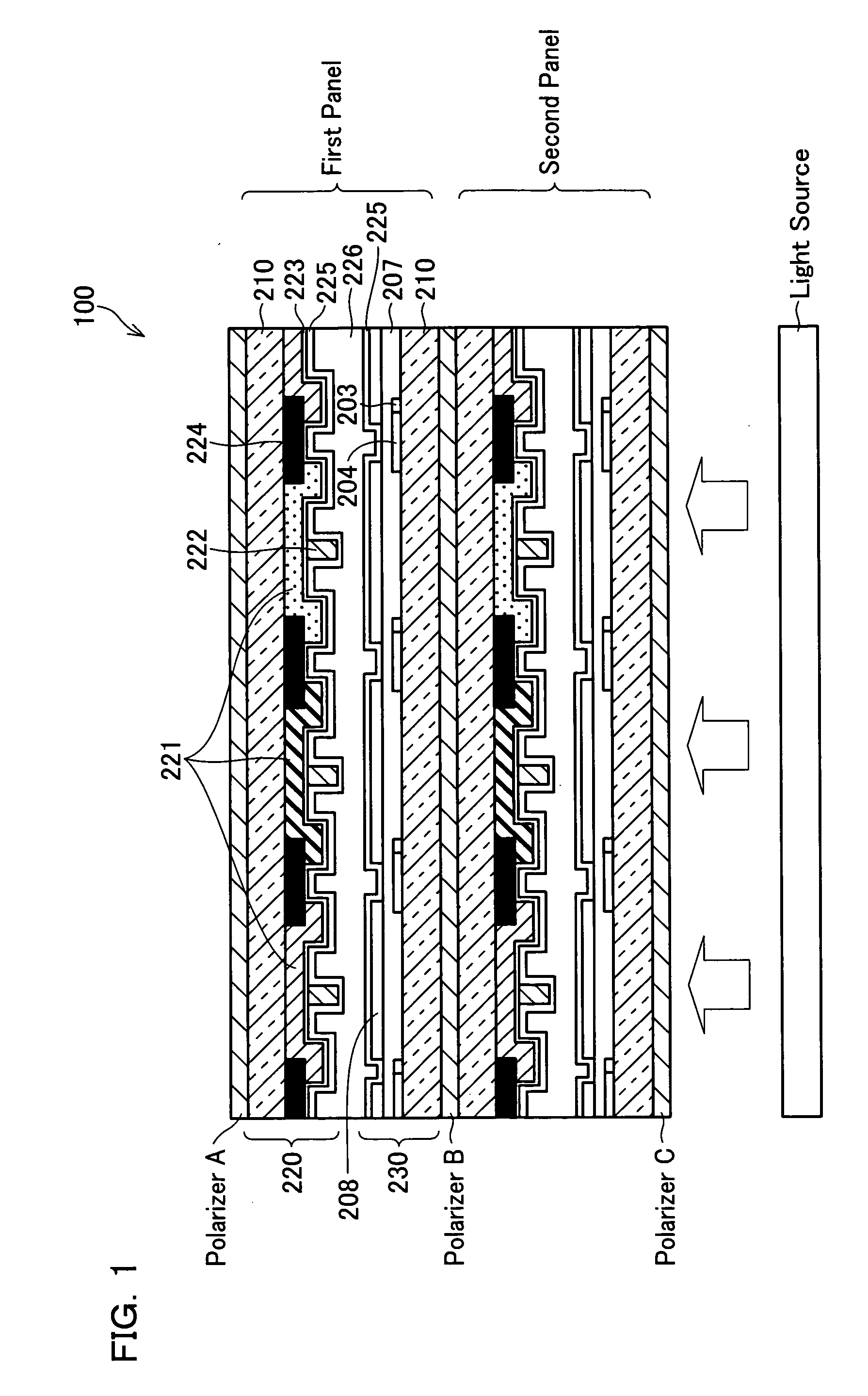
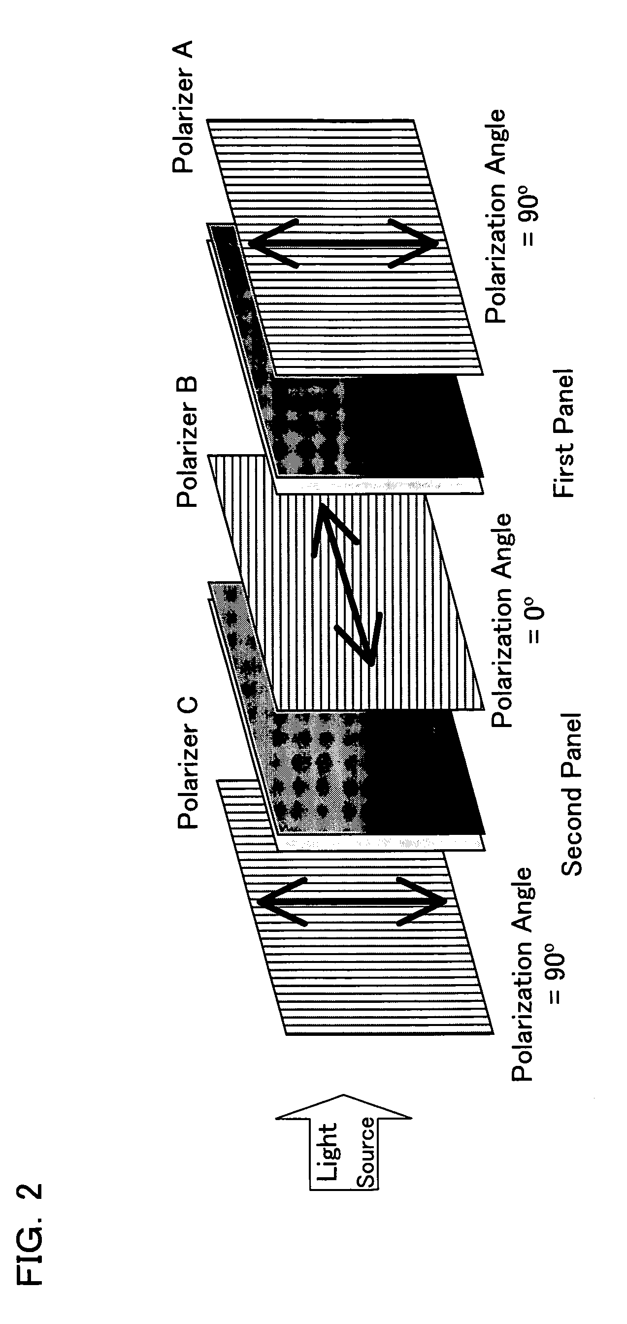
[0299]When the liquid crystal display 100 is configured as shown in FIG. 1 and polarizers and panels are combined as shown in FIG. 2, it becomes possible to restrain the degree of mutual non-synchronous interference of fine structures (e.g. alignment controlling projections), having equivalent cycles, which are provided on the adjacent panels, by forming the first panel and the second panel so that the pixel pattern on the first panel and the pixel pattern of the second panel are inverted symmetrically with each other as shown in FIG. 26. That restrains moire pattern occurrences attributable to structural interference, thereby preventing degradation of display quality attributable to moire patterns.
[0300]FIGS. 27(a) to 27(d) show examples of the pixels of the first panel overlapping those of the second panel.
[0301]The alignment controlling projections and electrode slits transmit almost no light. Therefore, if the pixels are not inverted, there is a large change in transmittance bet...
PUM
| Property | Measurement | Unit |
|---|---|---|
| haze | aaaaa | aaaaa |
| haze | aaaaa | aaaaa |
| haze | aaaaa | aaaaa |
Abstract
Description
Claims
Application Information
 - R&D
- Intellectual Property
- Life Sciences
- Materials
- Tech Scout
- Unparalleled Data Quality
- Higher Quality Content
- 60% Fewer Hallucinations
Browse by: Latest US Patents, China's latest patents, Technical Efficacy Thesaurus, Application Domain, Technology Topic, Popular Technical Reports.
© 2025 PatSnap. All rights reserved.Legal|Privacy policy|Modern Slavery Act Transparency Statement|Sitemap|About US| Contact US: help@patsnap.com