
Method and apparatus for repeaterless high-speed optical transmission over single-mode fiber using coherent receiver and electronic dispersion compensation

a repeaterless, optical transmission technology, applied in the field of repeaterless optical transmission over single-mode fiber, can solve the problems of fiber loss, fiber nonlinearity, chromatic dispersion (cd), etc., and achieve linear microwave dispersion compensation, eliminate additional link loss, and high sensitivity

Active Publication Date: 2009-06-04
DISCOVERY SEMICON
View PDF21 Cites 20 Cited by
  • Summary
  • Abstract
  • Description
  • Claims
  • Application Information

AI Technical Summary

Benefits of technology

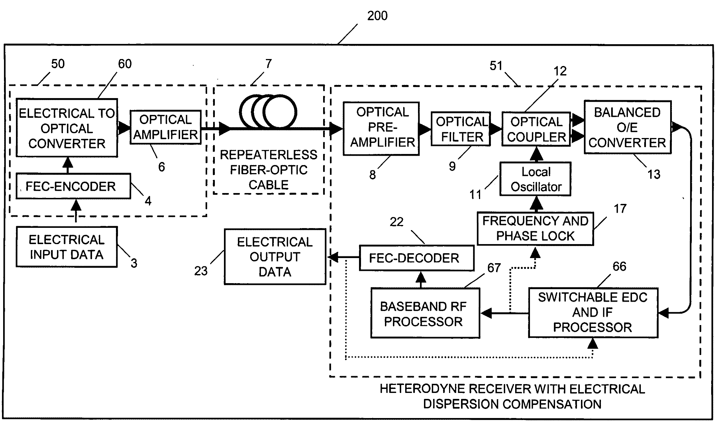
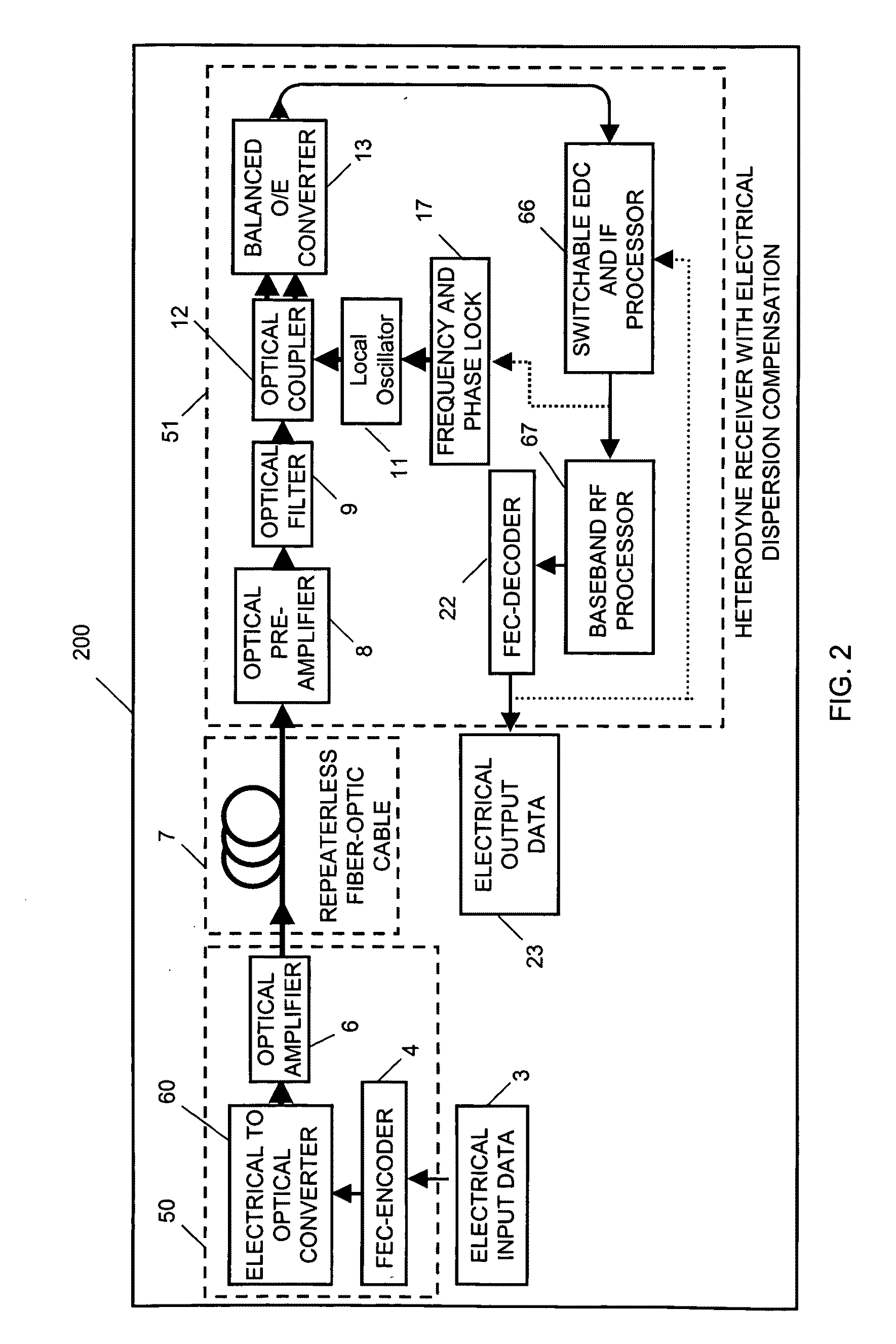
[0005]The present invention relates generally to a repeaterless 10.7 Gb / s non-return-to-zero (NRZ) differential phase-shift keying (DPSK) transmission system and method of implementing the same. Our inventive system provides repeaterless transmission of 10.7 Gb / s differential phase-shift keying (DPSK) over 304 km of SSMF, which is a record to the best of our information and knowledge. This is achieved by using DPSK in combination with coherent detection and electronic dispersion compensation. DPSK provides high sensitivity and allows high fiber launch power to overcome link losses of up to 60 dB. No in-line amplifiers, remotely pumped Erbium doped fiber amplifiers (EDFAs), or Raman amplifiers are necessary. The heterodyne receiver used in our experiments both preserves the optical phase distortions due to chromatic dispersion, and enables linear microwave dispersion compensation in the electrical domain. Such a compensation scheme eliminates any additional link loss associated with the use of in-line optical dispersion compensating modules (DCM). At a transmission distance of over 304 km of SSMF, we confirmed that our system has a margin of 3 dB considering the most simple Reed-Solomon forward error correction (FEC) code RS(255,239) which requires a minimum bit error rate (BER) of 1.8e-4 (Q-factor of 11 dB).
[0009]heterodyne detection means connected between an output of said receiver and an input to said dispersion compensation means, said detection means providing preservation of the phase distortions arising from chromatic dispersion to permit use of said electronic dispersion compensation.

Problems solved by technology

The fiber loss, fiber nonlinearities, and chromatic dispersion (CD) of the widely deployed standard single-mode fiber (SSMF) are the biggest hurdles to design and implement long-haul repeaterless terrestrial transmission systems operating at about 1550 nm.

Method used


Image

  • Method and apparatus for repeaterless high-speed optical transmission over single-mode fiber using coherent receiver and electronic dispersion compensation
  • Method and apparatus for repeaterless high-speed optical transmission over single-mode fiber using coherent receiver and electronic dispersion compensation
  • Method and apparatus for repeaterless high-speed optical transmission over single-mode fiber using coherent receiver and electronic dispersion compensation

Examples


Embodiment Construction

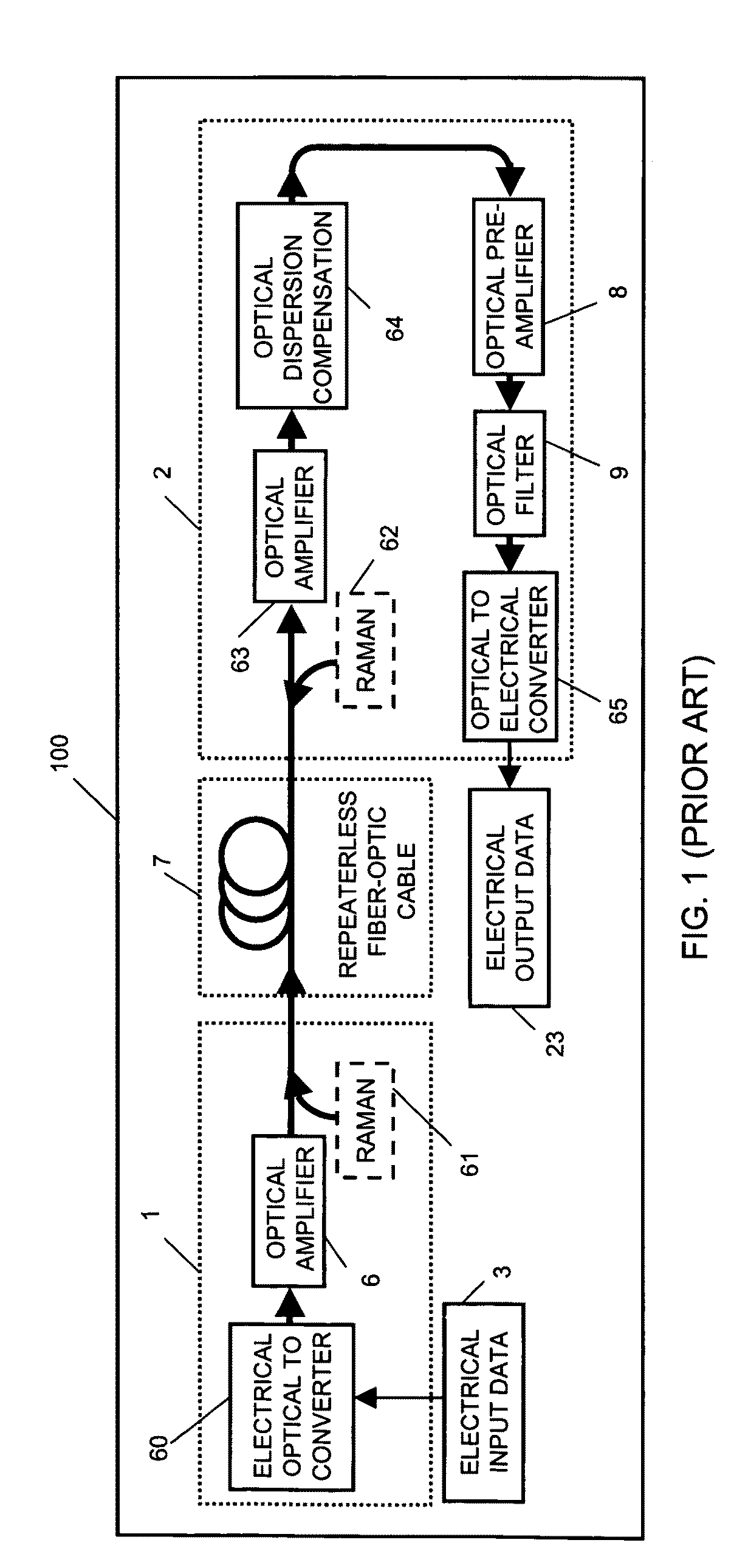
[0016]A known repeaterless optical transmission system is shown in the block schematic diagram of FIG. 1. As shown, the prior system 100 provides an optical transmitter 1 including an electrical-to-optical converter 60 for converting an electrical input data 3 into an optical signal, which in turn is fed to a lumped optical amplifier 6. Optionally, a distributed Raman amplification process 61 is used after the lumped optical amplifier 6 before the optical signal is inputted into one end of a repeaterless fiber-optic cable or span 7. An optical receiver 2 receives the optical signal from the output, or other end of the repeaterless fiber-optic span 7. Receiver 2 optionally feeds the optical signal to a distributed Raman amplification process 62, the output of which is connected to an optical amplifier 63 to compensate for the loss of the repeaterless fiber-optic cable or fiber-optic span 7. If the Raman application process is not used, the optical signal is connected directly to the ...


PUM


Abstract

Repeaterless transmission of differential phase-shift keying (DPSK) at 10.7 Gb / s over at least 304 km of standard single-mode fiber is obtained through use of a coherent optical receiver including electronic dispersion compensation. High receiver sensitivity and high tolerance to nonlinearities of DPSK, allow overcoming a total link loss of 58 dB with a 3 dB system margin, through use in the receiver of heterodyne detection to preserve phase distortions resulting from chromatic dispersion, to permit electronic dispersion compensation to be used.

Description

RELATED APPLICATION[0001]This application is related to and takes priority from co-pending Provisional Application No. 61 / 002,263, filed on Nov. 7, 2007, and is related to Becker et al. U.S. Pat. No. 7,406,269, issued on Jul. 29, 2008, the teachings of each of which are incorporated by reference herein to the extent they do not conflict herewith. The related Provisional Application has the same inventorship and assignee as the present application. The related Becker et al. U.S. Pat. No. 7,406,269 has the same assignee as the present application.FIELD OF THE INVENTION[0002]The present invention relates to signal transmission systems and methods of implementing the same, and more particularly to a repeaterless 10.7 Gb / s non-return-to-zero (NRZ) differential phase-shift keying (DPSK) transmission.BACKGROUND OF THE INVENTION[0003]Repeaterless transmission enables less complex systems not only for submarine but also for terrestrial fiber optical communications. The fiber loss, fiber nonl...

Claims


Application Information

Patent Timeline
IPC IPC(8): H04B10/12H04B10/148
CPCH04B10/25133H04B10/64H04B10/6161H04B10/60
Inventor WREE, CHRISTOPH T.BHANDARE, SUHAS P.BECKER, DONALD A.MOHR, DANIEL R.JOSHI, ABHAY M.
Owner DISCOVERY SEMICON
Learn More