
Apparatus and method for receiver in multiple antenna system

Active Publication Date: 2009-06-04
SAMSUNG ELECTRONICS CO LTD
View PDF1 Cites 13 Cited by
  • Summary
  • Abstract
  • Description
  • Claims
  • Application Information

AI Technical Summary

Benefits of technology

[0031]Another aspect of the present invention is to provide an apparatus and a method for reducing a computational complexity in calculating Euclidean distances in a MIMO system.
[0032]Yet another aspect of the present invention is to provide an apparatus and a method for preventing abnormal operations in calculating a Log Likelihood Ratio (LLR) in a MIMO system.

Problems solved by technology

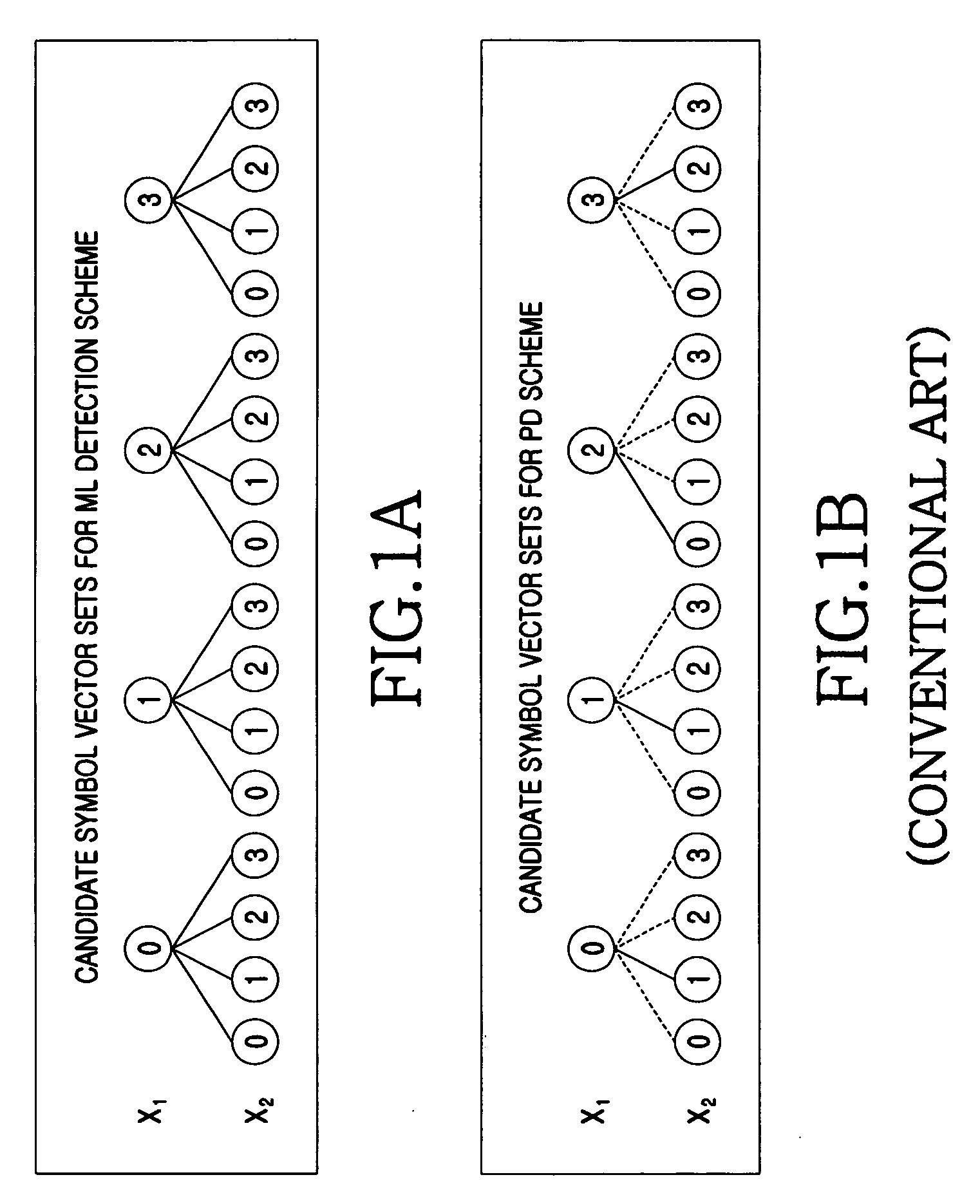
When transmitters send different data streams using the SM scheme of the multi-antenna technology, interference occurs between the transmitted data.
In so doing, complicated detection is required.
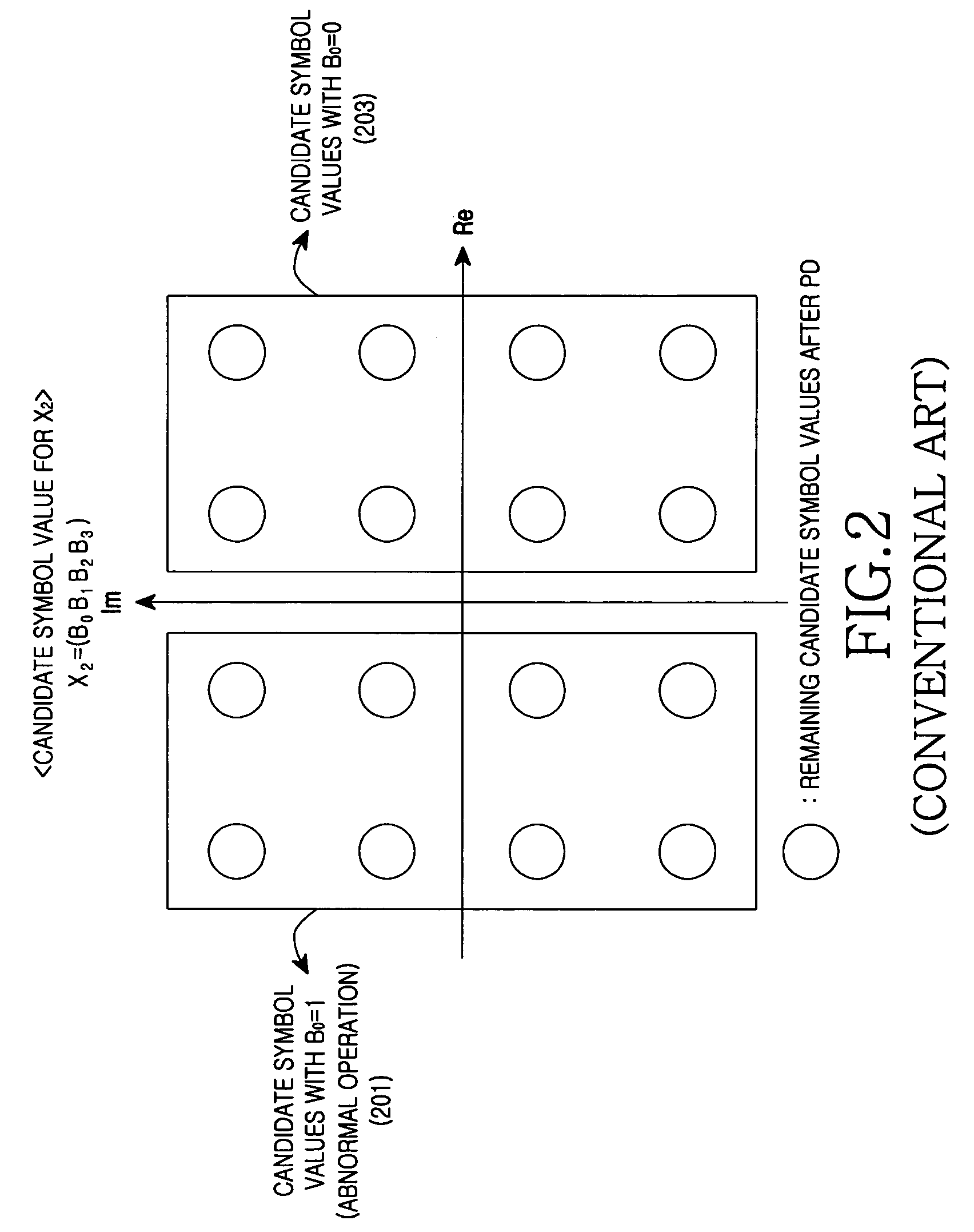
Disadvantageously, without considering channel decoding, when channel decoding is actually required, abnormal operations result in the LLR calculation.
Since there are no candidate symbol values for the first bit ‘1’ as shown in FIG. 2, abnormal operations result in the LLR calculation.
As a result, as the modulation order increases, the computational complexity is still problematic.

Method used


Image

  • Apparatus and method for receiver in multiple antenna system
  • Apparatus and method for receiver in multiple antenna system
  • Apparatus and method for receiver in multiple antenna system

Examples


Embodiment Construction

[0049]FIGS. 3 through 8B, discussed below, and the various embodiments used to describe the principles of the present disclosure in this patent document are by way of illustration only and should not be construed in any way to limit the scope of the disclosure. Those skilled in the art will understand that the principles of the present disclosure may be implemented in any suitably arranged wireless communication system.

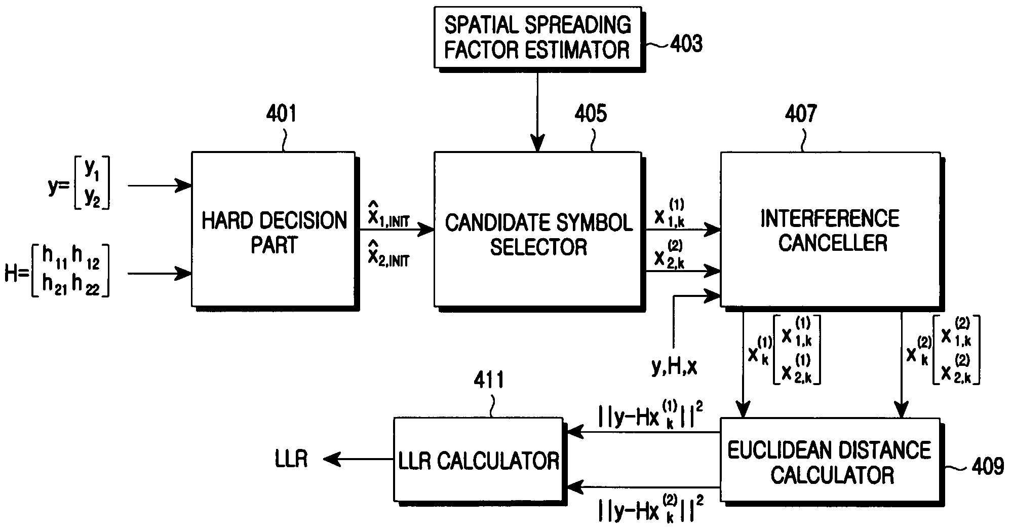
[0050]Exemplary embodiments of the present invention provide a receiving apparatus and a receiving method for adjusting the number of candidate symbol vectors according to a channel condition in a Multiple-Input Multiple-Output (MIMO) system.

[0051]FIG. 3 is a detailed block diagram of a multi-antenna receiving apparatus according to an exemplary embodiment of the present invention.

[0052]The receiving apparatus of FIG. 3 includes a certain number of receivers (that is, K-ary receivers 301 through 303), a Log Likelihood Ratio (LLR) generator 305, a deinterleaver 307, an...


PUM


Abstract

Detection apparatus and method for achieving performance close to a Maximum Likelihood (ML) detection having optimal performance and reducing computational complexity in a Multiple-Input Multiple-Output (MIMO) system including a plurality of transmit antennas and receive antennas are provided. The apparatus includes a hard decision part for confirming an initial hard decision value of a receive symbol vector; a candidate symbol selector for selecting candidate symbols restricted to neighbor values of the initial hard decision value; and an interference canceller for canceling interference in the selected candidate symbols and selecting a final candidate symbol from the received symbols using a result of the interference cancellation.

Description

CROSS-REFERENCE TO RELATED APPLICATION(S) AND CLAIM OF PRIORITY[0001]The present application claims the benefit under 35 U.S.C. §119(a) to a Korean patent application filed in the Korean Intellectual Property Office on Dec. 3, 2007 and assigned Serial No. 10-2007-0124193, the entire disclosure of which is hereby incorporated by reference.TECHNICAL FIELD OF THE INVENTION[0002]The present invention relates generally to a detection method and structure for achieving performance close to a Maximum Likelihood (ML) detection having an optimal performance and reducing a computational complexity in a Multiple-Input Multiple-Output (MIMO) system including a plurality of transmit antennas and receive antennas.BACKGROUND OF THE INVENTION[0003]Recently, rapid growth of the wireless mobile communication market requires various multimedia services in a wireless environment. Particularly, massive transmit data and high-speed data delivery are in progress. In this respect, the most urgent task is t...

Claims


Application Information

Patent Timeline
IPC IPC(8): H04B1/10H04L27/06
CPCH04B7/0854H04L25/03178H04L27/38H04L25/061H04L25/03318H04B7/08H04L1/02
Inventor YANG, JOO-YEOLKIM, SUNG-SOO
Owner SAMSUNG ELECTRONICS CO LTD
Learn More