
Heat sink and method for producing a heat sink

a heat sink and heat sink technology, applied in the field of heat sinks, can solve the problems of large metallic heat sinks, large components, and high cost of reliable positioning and mechanic fixing prior to the soldering process, and achieve the effect of reducing the cost of reliable positioning and mechanic fixing, and reducing the cost of manufacturing

Inactive Publication Date: 2009-06-04
FRAUNHOFER GESELLSCHAFT ZUR FOERDERUNG DER ANGEWANDTEN FORSCHUNG EV
View PDF16 Cites 58 Cited by
  • Summary
  • Abstract
  • Description
  • Claims
  • Application Information

AI Technical Summary

Problems solved by technology

This results in a significant amount of components.
Additionally, the reliable positioning and mechanic fixing prior to the soldering process is expensive.
Additionally, due to their large heat capacity, large metallic heat sinks have negative influences on the soldering process.
The attachment of individual cooling elements or the flat assembly of printed circuit boards on cooling elements by adhering or clamping is not compatible to the common assembly processes of electronics production and necessitates additional, mostly manual and, thus, expensive assembly steps.
Apart from this, large-area adhering of printed circuit board and heat sink causes significant thermal-mechanical tensions due to the different coefficients of thermal expansion of the materials.
Thus, the resistance to temperature changes of such an assembly is very limited.

Method used


Image

  • Heat sink and method for producing a heat sink
  • Heat sink and method for producing a heat sink
  • Heat sink and method for producing a heat sink

Examples


first embodiment

[0039]Since plastics have no or only very little adhesion to metal surfaces, de-lamination of the plastic from the metal can occur, in particular during tension due to temperature changes, due to the resulting thermo-mechanical tension at the plastic-metal interface, because of different coefficients of thermal expansion. This would significantly decrease the heat transition from metal to plastic. Thus, in a first embodiment, for improving the adhesion between metal-plastic elements, an inventive cooling element can be provided with a mechanical clamp for improving the connection. This can, for example, be obtained by specifically introduced openings 70 in the metallic molded part 2 (see FIG. 7). The openings 70 are circular or have a different shape and extend through the whole molded part.

second embodiment

[0040]In a second embodiment, for improving the connection, an additional adhesive layer can be deposited on the metallic molded part 2 (e.g. via ultramid 1C).

[0041]Since in many filling materials, an increase of the thermal connectivity is accompanied by an increase of the electric conductivity (e.g. with graphite), the heat sink can also be realized via a multilayer structure. Thus, an inventive cooling element can be realized, e.g., by a two-layer structure. The same consists then of an advantageous thin unfilled (and thus non-conductive) layer, which lies between the metallic molded part and a second filled layer forming the residual heat sink.

[0042]In this embodiment, the base body is conductive but electrically insulated from the molded part. In a first embodiment, this multilayer heat sink can be realized by thin electrically insulating film, which is inserted in parallel to the punch grid in the injection molding process and is molded as well. In a second embodiment, the sam...


PUM

PropertyMeasurementUnit
Distanceaaaaaaaaaa
Electrical conductivityaaaaaaaaaa
Sizeaaaaaaaaaa

Abstract

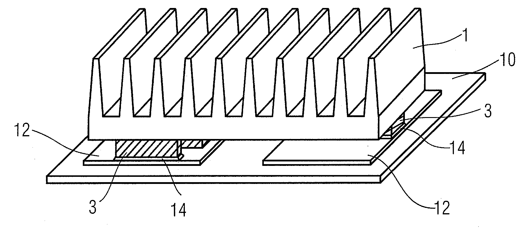
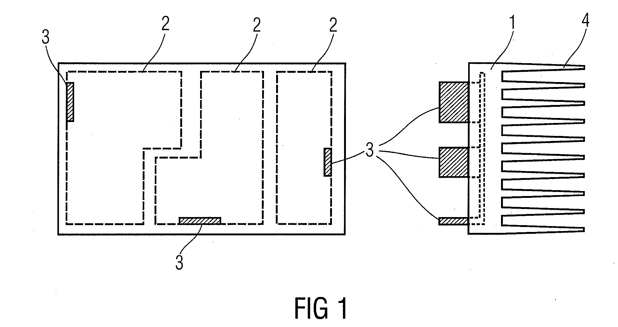
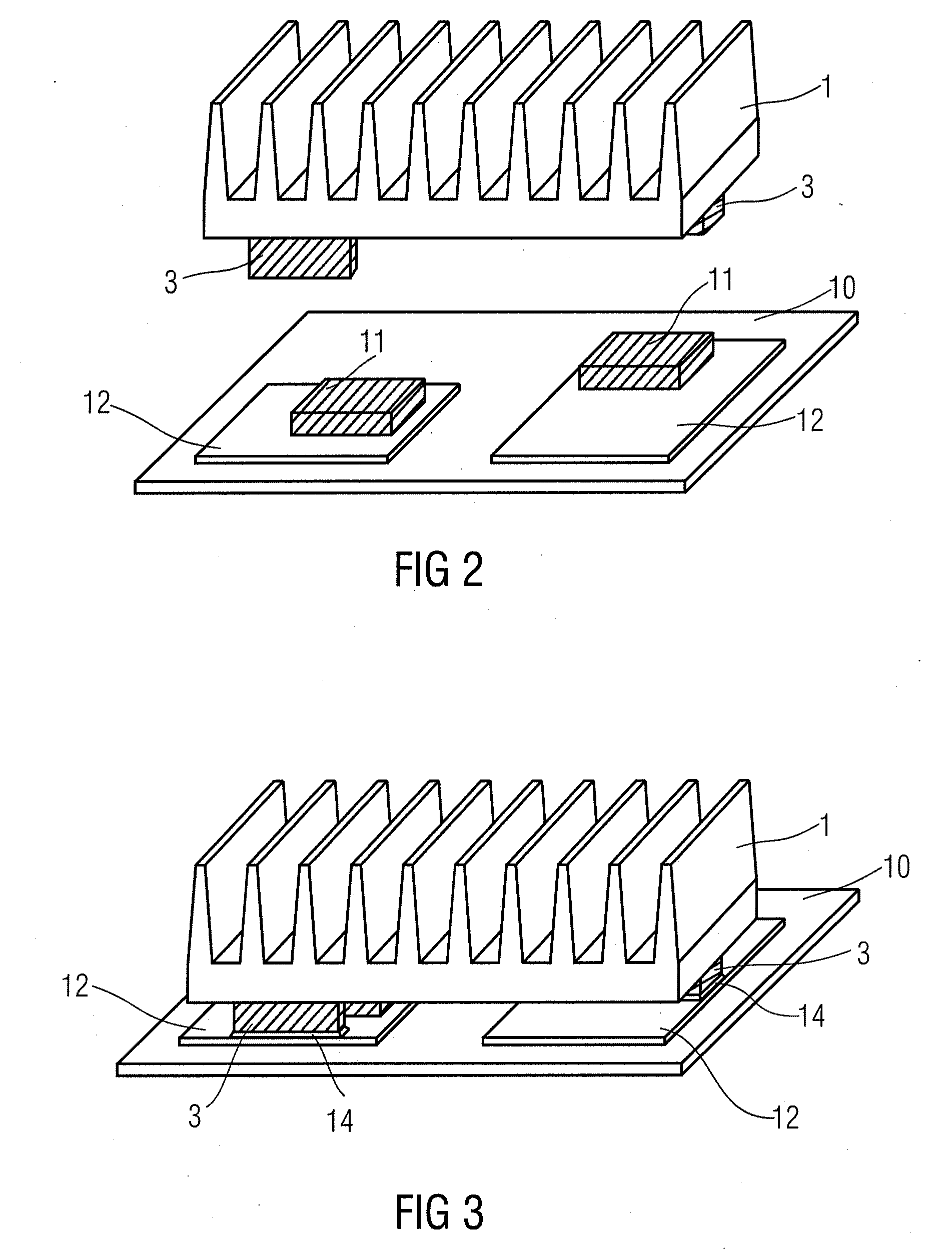
A heat sink includes a base body of an electrically insulating material and one or several metallic molded parts having a mounting portion and a heat-transfer portion, wherein the heat-transfer portion is mechanically connected to the base body. The heat sink can be inserted on a printed circuit board having several heat sources that can be at different electrical potentials, wherein the mounting portions of the molded parts are soldered to respective heat sources or close to the respective heat sources.

Description

CROSS-REFERENCE TO RELATED APPLICATIONS[0001]This application claims priority from German Patent Application No. 102007057533.7, which was filed on Nov. 29, 2007, and is incorporated herein in its entirety by reference.BACKGROUND OF THE INVENTION[0002]The invention relates to a heat sink and, particularly, to a heat sink for electronic circuits and a method for producing the same.[0003]Heat sinks are frequently used for cooling electronic circuits. It is the object of a heat sink to improve heat dissipation by increasing the surface. Thereby, heat dissipation can take place both via convection—to a liquid or gaseous cooling medium—and by radiation.[0004]Metal heat sinks, mostly of aluminum or copper, are used for cooling electronic assemblies. The devices generating power dissipation are thermally coupled to these heat sinks. If several devices are to be cooled, the same have to be mounted electrically insulated from each other, but in a thermally high-conductive manner to the heat ...

Claims


Application Information

Patent Timeline
IPC IPC(8): F28F7/00F28F13/18B21D53/02B23P11/00
CPCH01L23/367H01L23/3672H01L23/373H05K7/20509Y10T29/49826H01L2924/0002Y10T29/4935H01L2924/00
Inventor MAERZ, MARTINTCHOBANOV, DIMITARECKHARDT, BERNDZELTNER, STEFANEGELKRAUT, SVENAMESOEDER, SIMON
Owner FRAUNHOFER GESELLSCHAFT ZUR FOERDERUNG DER ANGEWANDTEN FORSCHUNG EV
Learn More