
Automatic analyzer and analysis method for use in the same

a technology of automatic analyzer and analyzer, which is applied in the direction of chemical methods analysis, instruments, material analysis, etc., can solve the problems of increased size and cost of analyzer, inability to adapt the disclosed method, and complicated structure of analyzer, etc., and achieves high analysis efficiency.

Inactive Publication Date: 2009-05-28
YAMAZAKI ISAO +1
View PDF2 Cites 12 Cited by
  • Summary
  • Abstract
  • Description
  • Claims
  • Application Information

AI Technical Summary

Benefits of technology

[0008]It is an object of the present invention to provide an automatic analyzer capable of suppressing a reduction in processing capability regardless of the sequence of requested analysis items even when the analyzer is provided with a mechanism for dispensing plural kinds of reagents, which are to be added at different timings, by using the same reagent dispensing probe.
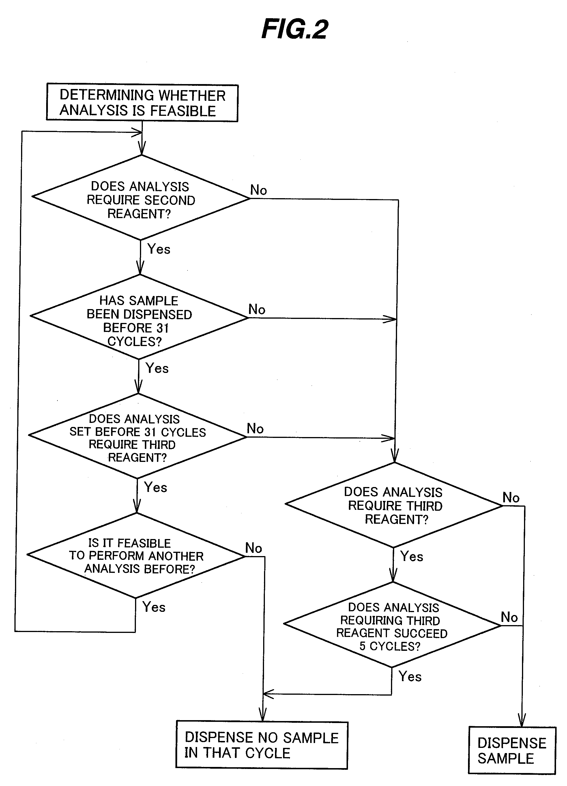
[0017]According to the present invention, even when there are mixed analyses requiring reagents to be dispensed at a plurality of different timings, cycles in which analysis is infeasible are avoided from succeeding over a large number, and therefore a high-speed automatic analyzer with high analysis efficiency can be provided.

Problems solved by technology

Looking it from the other side, the disclosed method is not adapted for the case of an analysis item in which the second reagent and the third reagent must be dispensed during one cycle.
If separate reagents probes dedicated for the second reagent and the third reagent are provided to avoid the above-mentioned problem, the analyzer would be complicated in structure, and the size and cost of the analyzer would be increased.
If the reagent dispensing is performed twice during one cycle, another problem of a reduction in analysis processing speed would arise.

Method used


Image

  • Automatic analyzer and analysis method for use in the same
  • Automatic analyzer and analysis method for use in the same
  • Automatic analyzer and analysis method for use in the same

Examples


Embodiment Construction

[0021]Embodiments of the present invention will be described below with reference to the drawings.

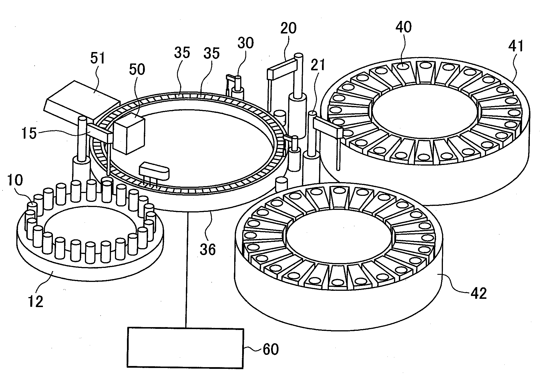
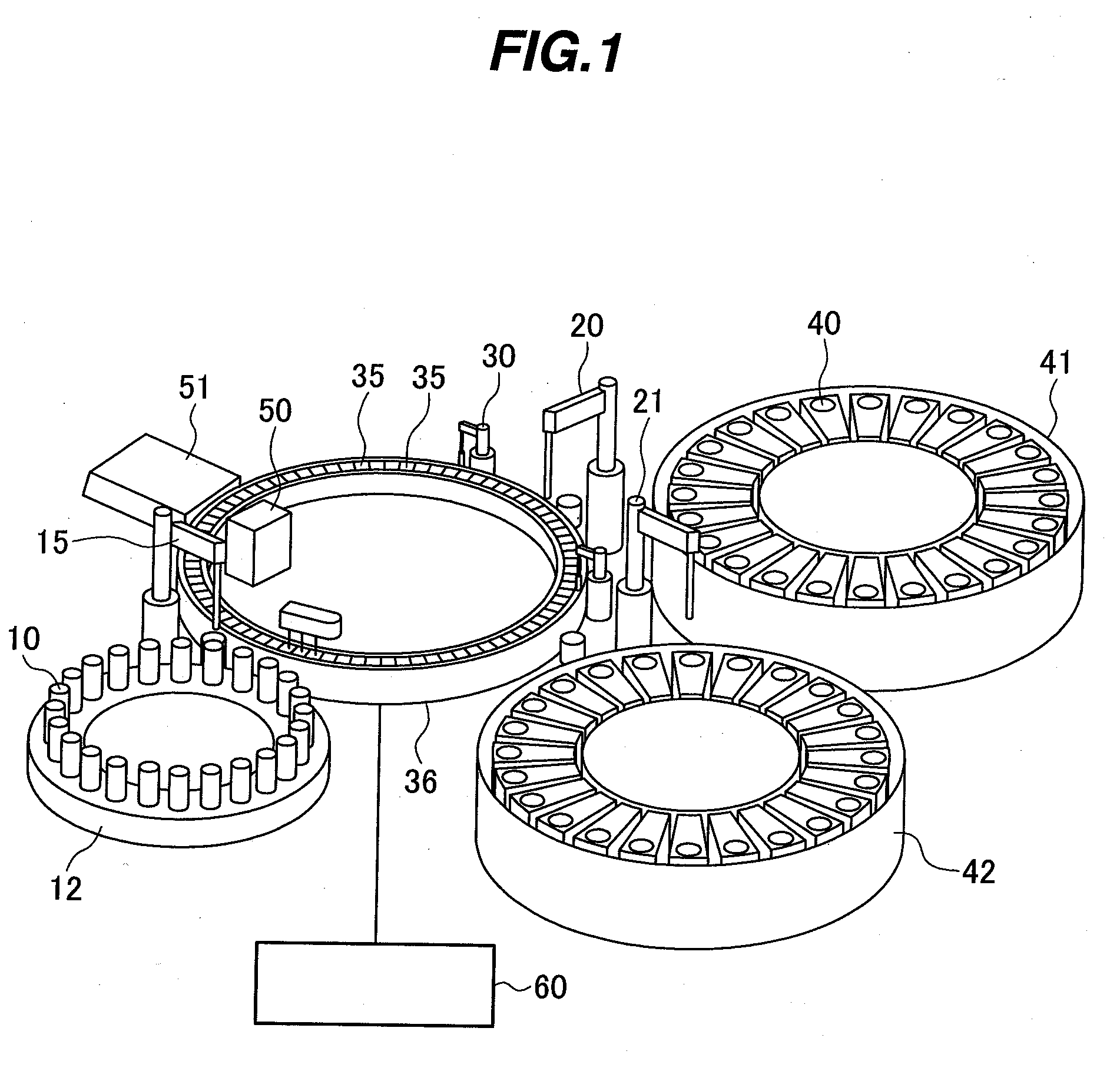
[0022]FIG. 1 shows one embodiment of an automatic analyzer to which the present invention is applied.

[0023]The automatic analyzer comprise a sample disk 12 on which a plurality of sample cups 10 each containing a sample are mountable; a first reagent disk 41 and a second reagent disk 42 on each of which a plurality of reagent bottles 40 each containing a reagent are mountable; a reaction disk 36 holding a number 160 of reaction cells 35 which are arranged along a disk circumference; a sample probe 15 for sucking the sample from the sample cup 10 and dispensing the sucked sample into the reaction cell 35; a first reagent probe 20 for sucking a reagent from one reagent bottle 40 on the first reagent disk 41 and dispensing the sucked reagent into the reaction cell 35; a second reagent probe 21 for sucking a reagent from another reagent bottle 40 on the second reagent disk 42 and dispensing...


PUM

PropertyMeasurementUnit
timeaaaaaaaaaa
circumferenceaaaaaaaaaa
sizeaaaaaaaaaa

Abstract

An automatic analyzer having a high processing capability even when plural kinds of reagents are dispensed at different timings. The automatic analyzer comprises a plurality of reaction cells, a reaction cell moving unit for moving the plurality of reaction cells at a certain cycle; a sample dispensing unit for dispensing a sample into a reaction cell on the reaction cell moving unit, a reagent dispensing unit for dispensing plural kinds of reagents to be added during a sample—reagent reaction process at different timings, the number of the reagent addition timings being larger than the number of times at which the reagents can be dispensed within a time of one cycle, and a control unit for controlling the sample dispensing unit to set a cycle in which no sample is dispensed by the sample dispensing unit, when analyses each using the reagent to be dispensed at the latest one of the reagent addition timings by the reagent dispensing unit succeed a predetermined number of times or more.

Description

BACKGROUND OF THE INVENTION[0001]1. Field of the Invention[0002]The present invention relates to an automatic analyzer for performing quantitative and qualitative analyses of components in a biological sample, such as blood and urine, and more particularly to an automatic analyzer provided with a mechanism for dispensing plural kinds of reagents, which are to be added at different timings, by using the same reagent dispensing probe.[0003]2. Description of the Related Art[0004]In an automatic analyzer for mixing a biological sample, such as blood and urine, with reagents in a reaction cell, and measuring a reaction solution to analyze items to be examined for the sample, a reagent dispensing probe is generally employed to supply the reagents from respective reagent bottles to the reaction cell.[0005]Patent Reference 1; JP,A 2003-21645, for example, discloses a method of adding reagents to a reaction cell in correspondence to items to be examined. More specifically, reaction cells are...

Claims


Application Information

Patent Timeline
Patent Type & Authority Applications(United States)
IPC IPC(8): G01N35/00G01N35/02G01N35/04G01N35/10
CPCG01N35/0092G01N35/02G01N35/025G01N35/10Y10T436/115831G01N2035/0097G01N2035/0444Y10T436/2575G01N35/1002G01N2035/0094
Inventor YAMAZAKI, ISAONISHIDA, MASAHARU
Owner YAMAZAKI ISAO
Learn More