Panel-type input device

Inactive Publication Date: 2009-05-28
FUJITSU COMPONENENT LTD
View PDF6 Cites 8 Cited by
  • Summary
  • Abstract
  • Description
  • Claims
  • Application Information

AI Technical Summary

Benefits of technology

[0009]It is an object of the present invention to provide a panel-type input device having a resistive-type configuration, which includes electrode plates provided with conductive coats having superior properties, such as impact resistance, writing durability, etc., and which is capable of preventing the conductive coats from sticking to each other due to a local pressing force applied by an input operation without degrading input operability.
[0011]According to the present invention, the panel-type input device, in which the conductive coat of at least one electrode plate is formed by using a conducting polymer, can possess superior properties of the conductive coat, such as impact resistance, writing durability, etc., compared to, e.g., a conventional touch panel in which both electrode plates are provided with ITO coats, and thus can ensure highly-precise and stable input operation for a long period. Further, since the dot spacers are formed in accordance with the specific A-value, it is possible to prevent the conductive coats from sticking to each other due to a local pressing force applied by an input operation without degrading input operability.

Problems solved by technology

If the conductive coats, having contacted with each other at the pressing point, do not separate from each other at an instant when the pressing force is relieved, input responsiveness of the touch panel is impaired.
However, both of these measures may increase a pressing force required for an input operation, which may lead to the degradation of operability of the touch panel.

Method used


Image

  • Panel-type input device
  • Panel-type input device
  • Panel-type input device

Examples


Embodiment Construction

[0019]The embodiments of the present invention are described below in detail, with reference to the accompanying drawings. In the drawings, the same or similar components are denoted by common reference numerals.

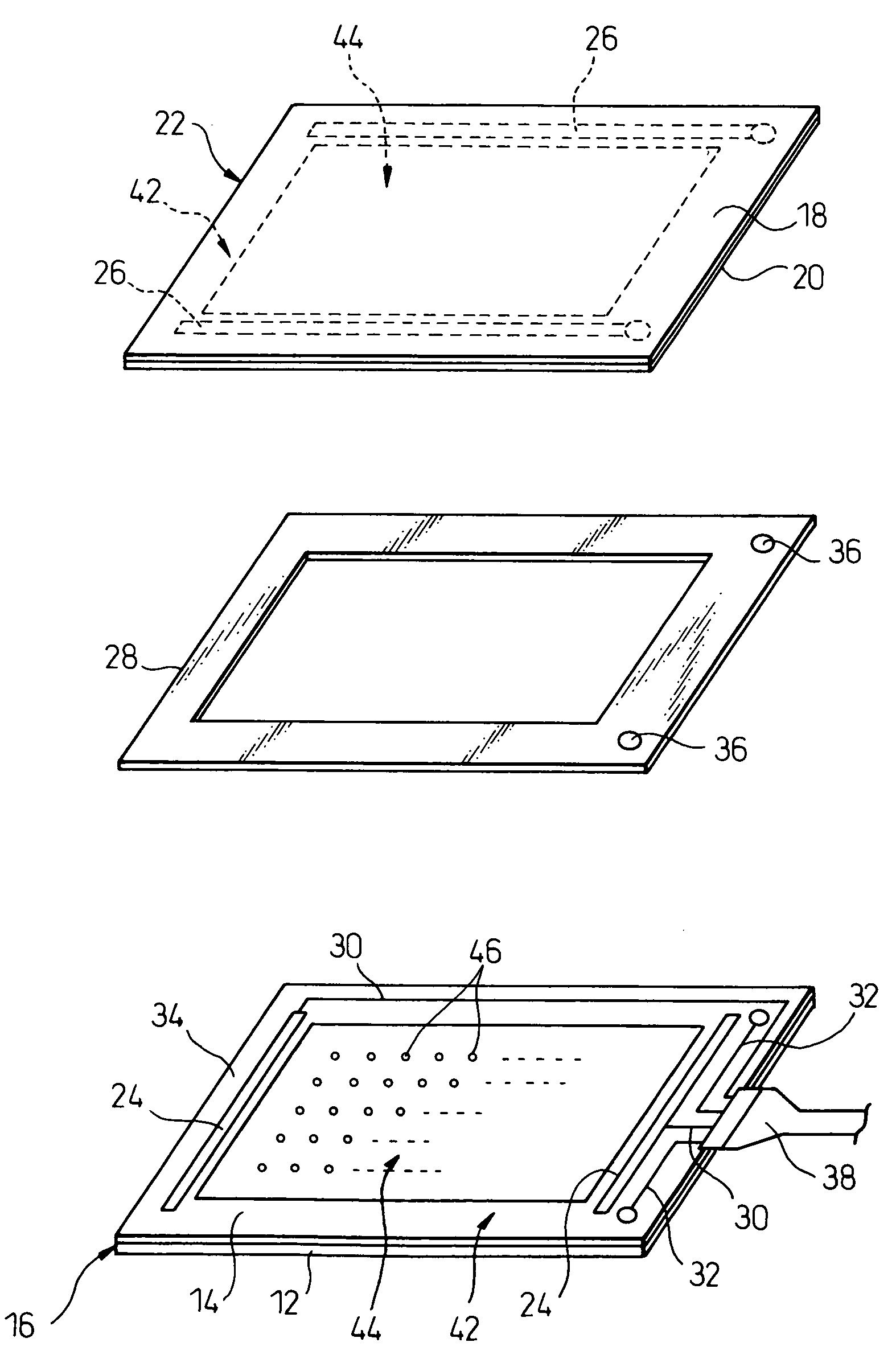
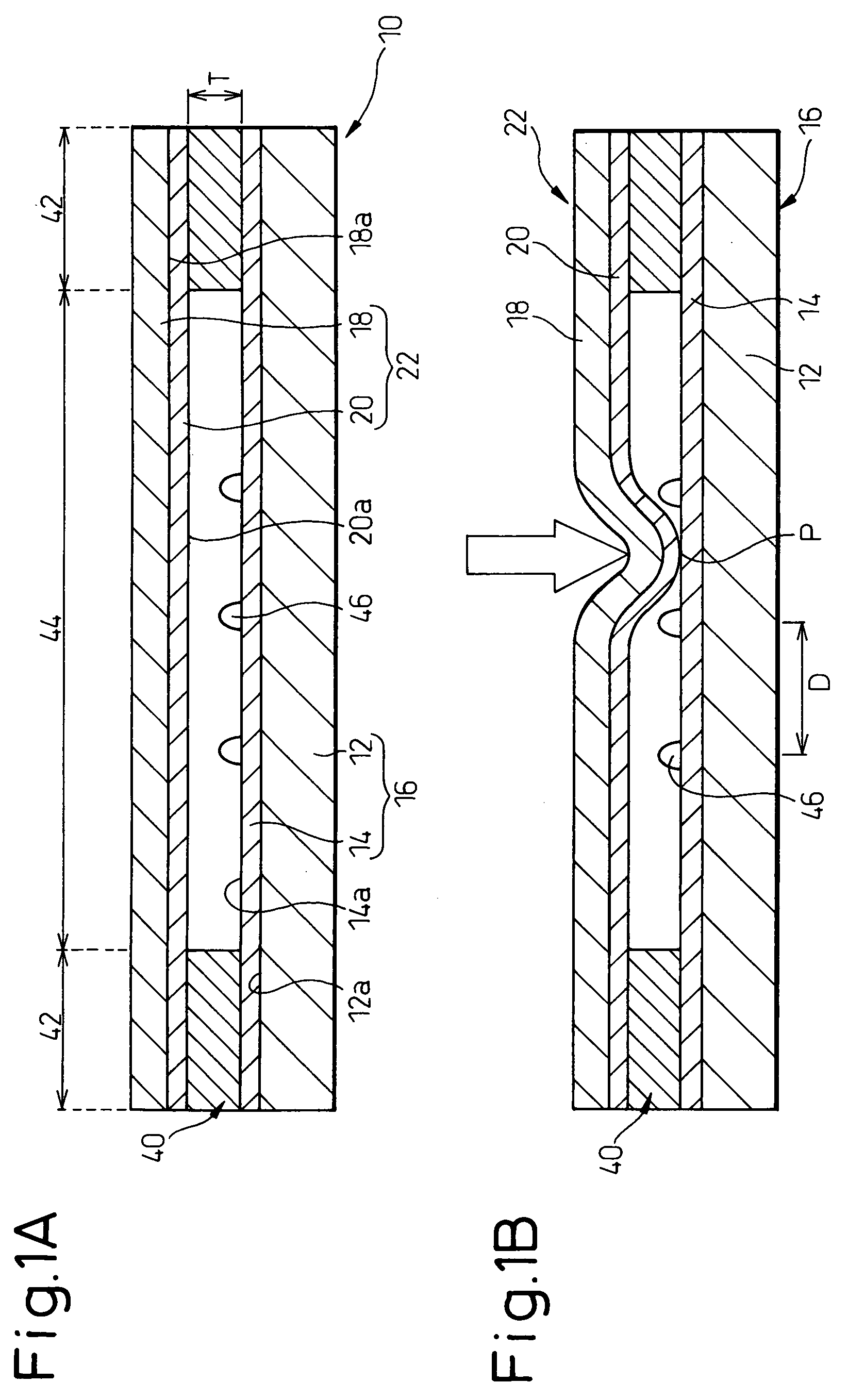
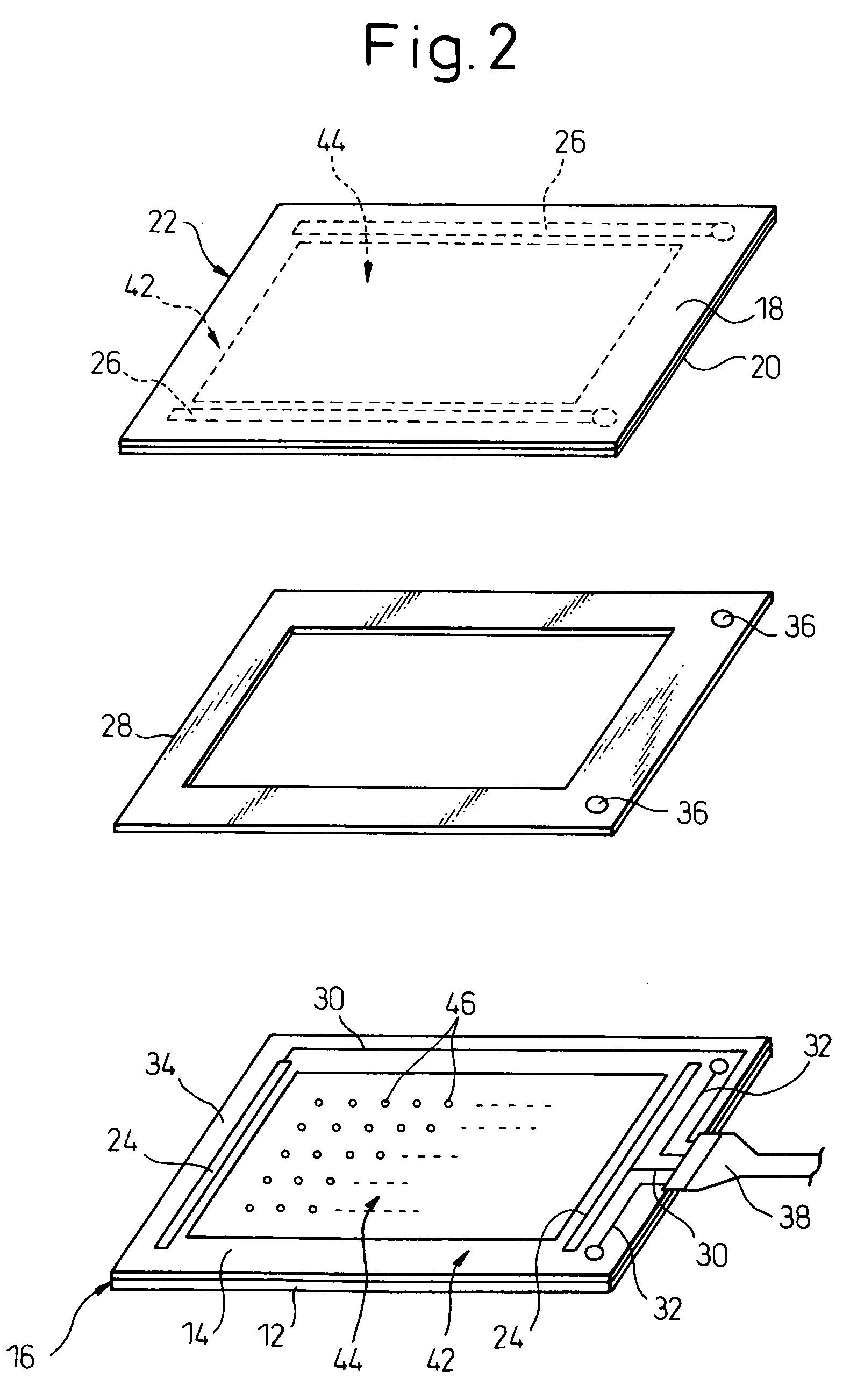
[0020]Referring to the drawings, FIGS. 1A and 1B show, in schematic sectional views, essential components of a panel-type input device 10 according to a first embodiment of the present invention in non-operated and operated states, and FIG. 2 shows, in an exploded schematic perspective view, the essential components of the panel-type input device 10.

[0021]The panel-type input device 10 includes a first electrode plate 16 having a first electrical-insulating substrate 12 and a first electrical-conductive coat 14 provided on a surface 12a of the first substrate 12, a second electrode plate 22 having a second electrical-insulating substrate 18 and a second electrical-conductive coat 20 provided on a surface 18a of the second substrate 18. The first substrate 12 and first conduc...


PUM


Abstract

A panel-type input device including a pair of electrode plates, each electrode plate including a substrate and a conductive coat provided on a surface of the substrate; and a plurality of dot spacers formed in a dispersed arrangement on a surface of the conductive coat of at least one of the electrode plates. The electrode plates are assembled with each other in a relative arrangement such that respective conductive coats are opposed to and spaced from each other while permitting a conductive contact therebetween. The conductive coat of at least one of the electrode plates is formed by using a conducting polymer. The dot spacers are formed in such a manner that a value A=H / D, representing a relationship between an overall height Hμm of each dot spacer measured from the surface of the conductive coat, on which the dot spacers are formed, and a substantial disposition interval Dmm of the dot spacers on the surface, is in a range of 1.5<A<6.0.

Description

BACKGROUND OF THE INVENTION[0001]1. Field of the Invention[0002]The present invention relates to a panel-type input device.[0003]2. Description of the Related Art[0004]A panel-type input device has been known as an input device of an electronic apparatus including a display unit, such as a personal computer, a personal digital assistant (PDA), an automatic teller machine (ATM), etc., which is operated to indicate two-dimensional coordinate data in the display unit by an operator pressing a desired point on a panel surface with his finger or a pen. In particular, a panel-type input device with a transparent structure, which can be mounted on a screen of a display unit, such as a liquid crystal display (LCD), a plasma display panel (PDP), a cathode ray tube (CRT), etc., has been widely used as a touch panel, and in recent years, has been mounted on a portable terminal unit having a mobile-phone function.[0005]A resistive-type touch panel, as one example of a panel-type input device, i...

Claims


Application Information

Patent Timeline
IPC IPC(8): G06F3/041
CPCG06F3/045G06F1/1626G06F1/1643G06F3/0412
Inventor ENDO, MICHIKO
Owner FUJITSU COMPONENENT LTD
Why Eureka
Try Eureka