Information processing method and apparatus

Inactive Publication Date: 2006-10-17
CANON KK
View PDF13 Cites 14 Cited by
  • Summary
  • Abstract
  • Description
  • Claims
  • Application Information

AI Technical Summary

Benefits of technology

[0021]It is another object of the present invention to allow to perform a stable input operation even if the direction of an operator's line of sight is unstable.

Problems solved by technology

The above-described three-dimensional input device using a magnetic sensor or an optical sensor is generally expensive.
Furthermore, since the number of objects to be measured at a time is sometimes limited depending on the sensor being used, it is sometimes impossible to measure the input device using a sensor.
In addition, for example, in a three-dimensional input device using an optical sensor, measurement cannot be performed if a body or an object is present between a measuring apparatus and an object to be measured.
However, in the conventional method of moving a pointer using a two-dimensional input device in an image obtained by performing perspective transformation of a three-dimensional space, if the direction of the operator's line of sight is unstable, the designated direction of the pointer greatly changes in the three-dimensional space.
Accordingly, in order to exactly designate an object in a three-dimensional space, the operator must fix his head, resulting in pain for the operator.
That is, in order to perform a stable operation, it is necessary to fix the operator's head mounting the HMD 201, resulting in a pain for the operator.
Although the above-described example represents a case of VR application software using an HMD, similar problems will arise in MR application software or telepresence application software.
The above-described conventional approach cannot deal with such a problem because it presumes a state in which the position of the viewpoint and the direction of the line of sight are fixed.

Method used


Image

  • Information processing method and apparatus
  • Information processing method and apparatus
  • Information processing method and apparatus

Examples


Embodiment Construction

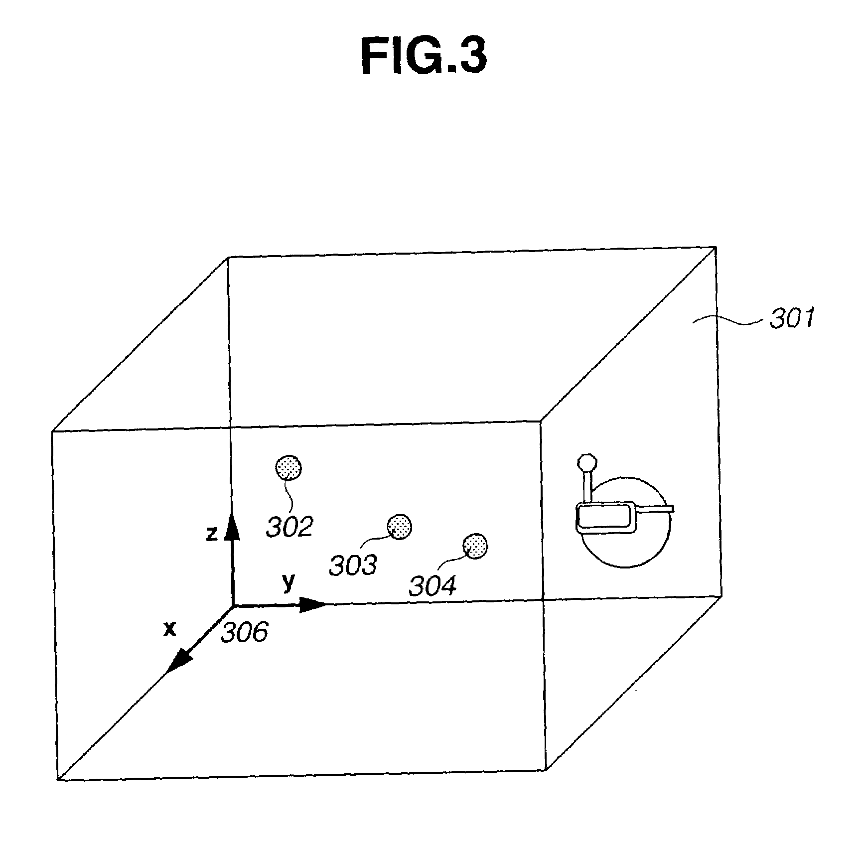
[0045]A preferred embodiment of the present invention will now be described with reference to the drawings. In this embodiment, the above-described VR application software in which the operator mounts an HMD and designates a virtual sphere present in a virtual three-dimensional space is used. However, an input method different from the above-described method is adopted. The input method of this embodiment can be applied to arbitrary VR or MR application software, or telepresence application software.

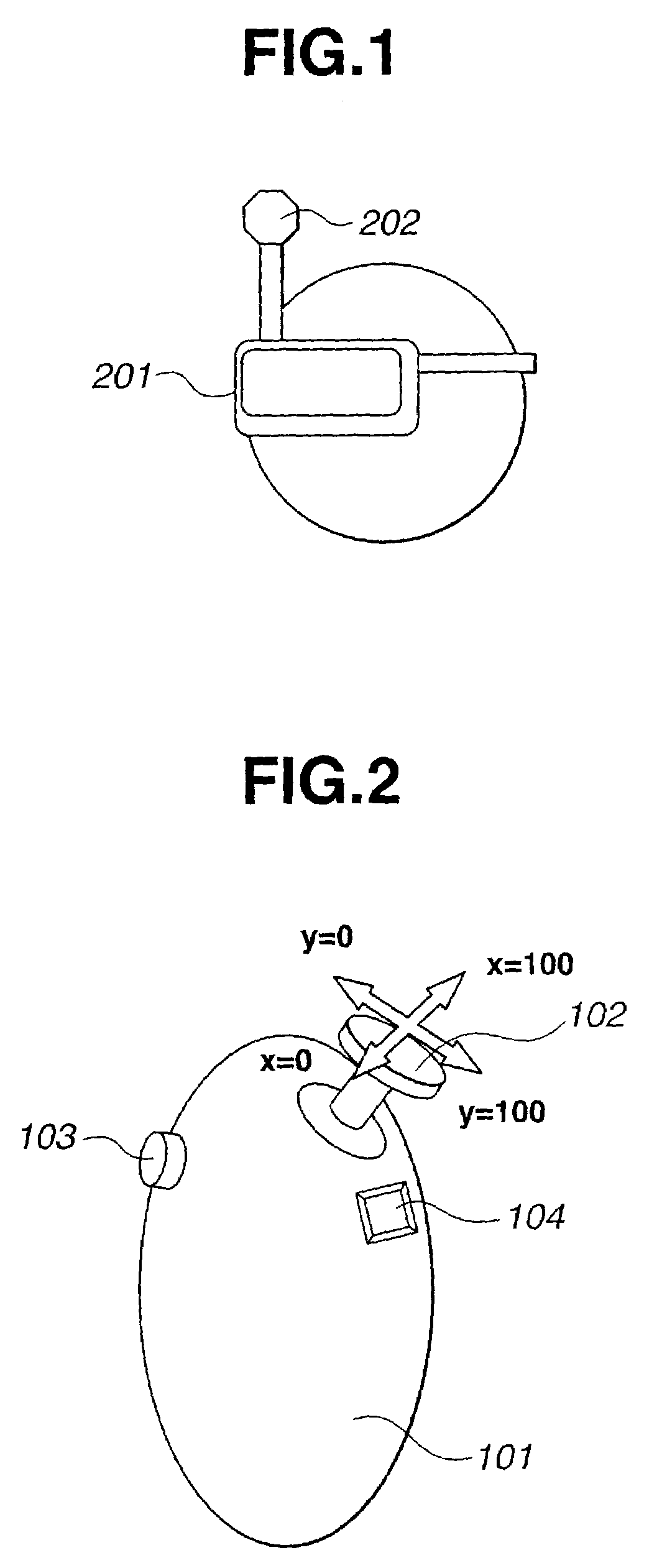
[0046]FIG. 9 is a block diagram illustrating an example of the configuration of the input method of the embodiment. In FIG. 9, there are shown a two-dimensional input device 101, a head position / posture sensor 202, an HMD 201, designated-direction determination means 901, designated-direction restoration means 902, designated-direction resetting means 903, and image generation means 904. Each of these units will now be described.

[0047]The two-dimensional input device 101 comprises, for e...


PUM


Abstract

It is intended to solve the problem that, when an operator performs an operation using two-dimensional input means while seeing a picture frame seen from a viewpoint of the operator, an input operation is difficult to perform when the direction of the line of sight of the operator is unstable, since a designated direction greatly deviates in a world coordinate system. For that purpose, viewpoint information is detected, and an instruction of the operator for operating a position of a pointer image is input. A designated direction in a pointer coordinate system is obtained in accordance with the operator's instruction, and the pointer image is generated based on the designated direction. The pointer coordinate system is changed from the detected viewpoint information in accordance with a specific instruction of the operator.

Description

BACKGROUND OF THE INVENTION[0001]1. Field of the Invention[0002]The present invention relates to an information processing method and apparatus for displaying an image in which a pointer image operated by an operator is synthesized.[0003]2. Description of the Related Art[0004]In virtual reality (VR), it is possible to see a three-dimensional virtual space from a viewpoint of an operator using a display, such as an HMD (head mounted display) or the like, and perform an operation in such an environment. In mixed reality (MR), an operator can see a real space and three-dimensional virtual space in a superposed state using a see-through HMD.[0005]In a telepresence system, an operator can perform an operation as if he is actually present at a remote location, by operating a camera provided at the remote location and performing the operation while seeing an image taken by the camera.[0006]In such VR, MR or a telepresence system, an operator sometimes performs an operation for a real or vi...

Claims


Application Information

Patent Timeline
IPC IPC(8): G09G5/00G09G5/08G02B27/00G06F3/033G02B27/01G06F3/0346
CPCG02B27/017G06F3/0338G06F3/04815G02B2027/0187G02B2027/0198
Inventor KUROKI, TSUYOSHIOHSHIMA, TOSHIKAZU
Owner CANON KK
Why Eureka
Try Eureka