
Fault detector and method of detecting faults

Active Publication Date: 2009-05-21
DELPHI TECH IP LTD
View PDF5 Cites 49 Cited by
  • Summary
  • Abstract
  • Description
  • Claims
  • Application Information

AI Technical Summary

Benefits of technology

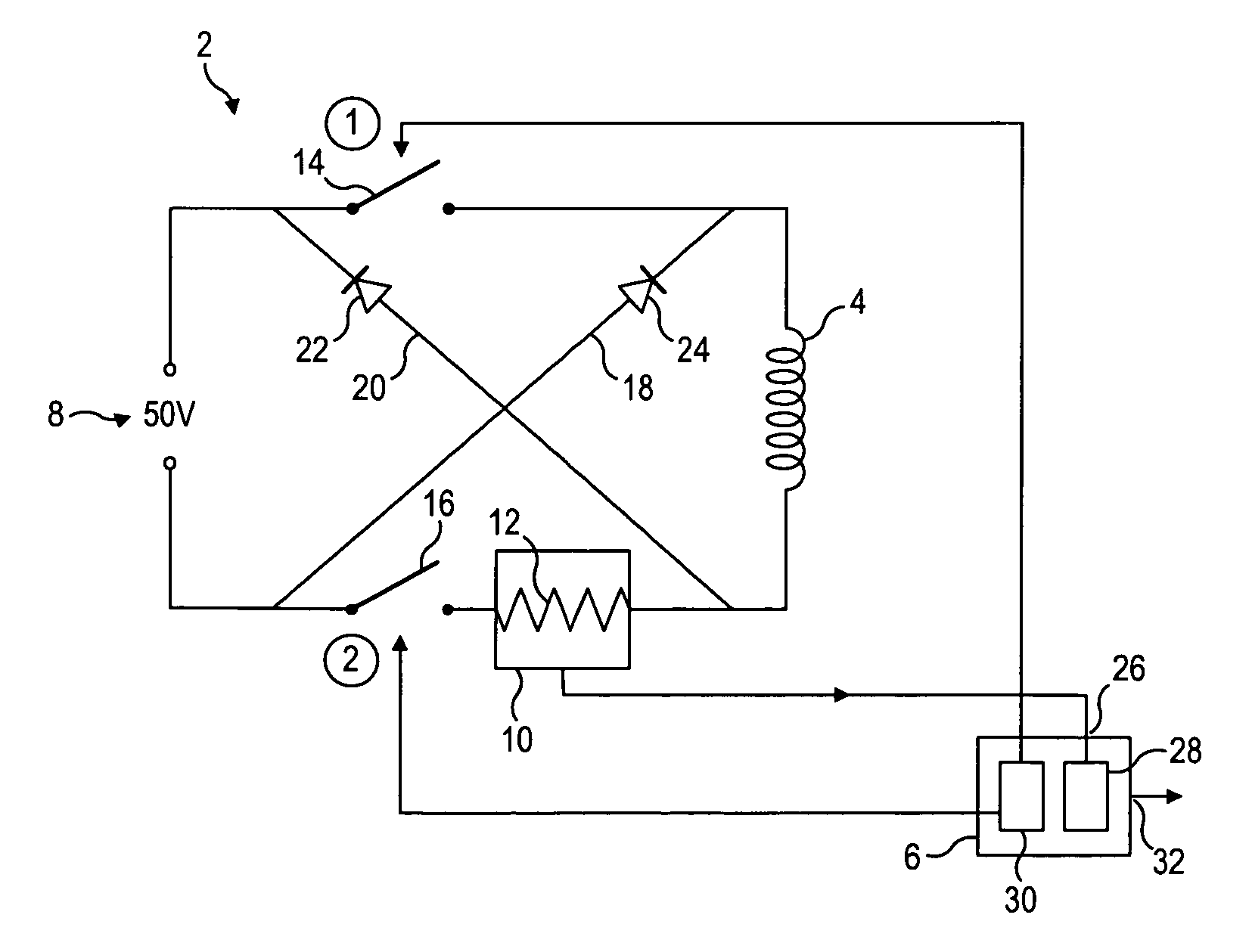
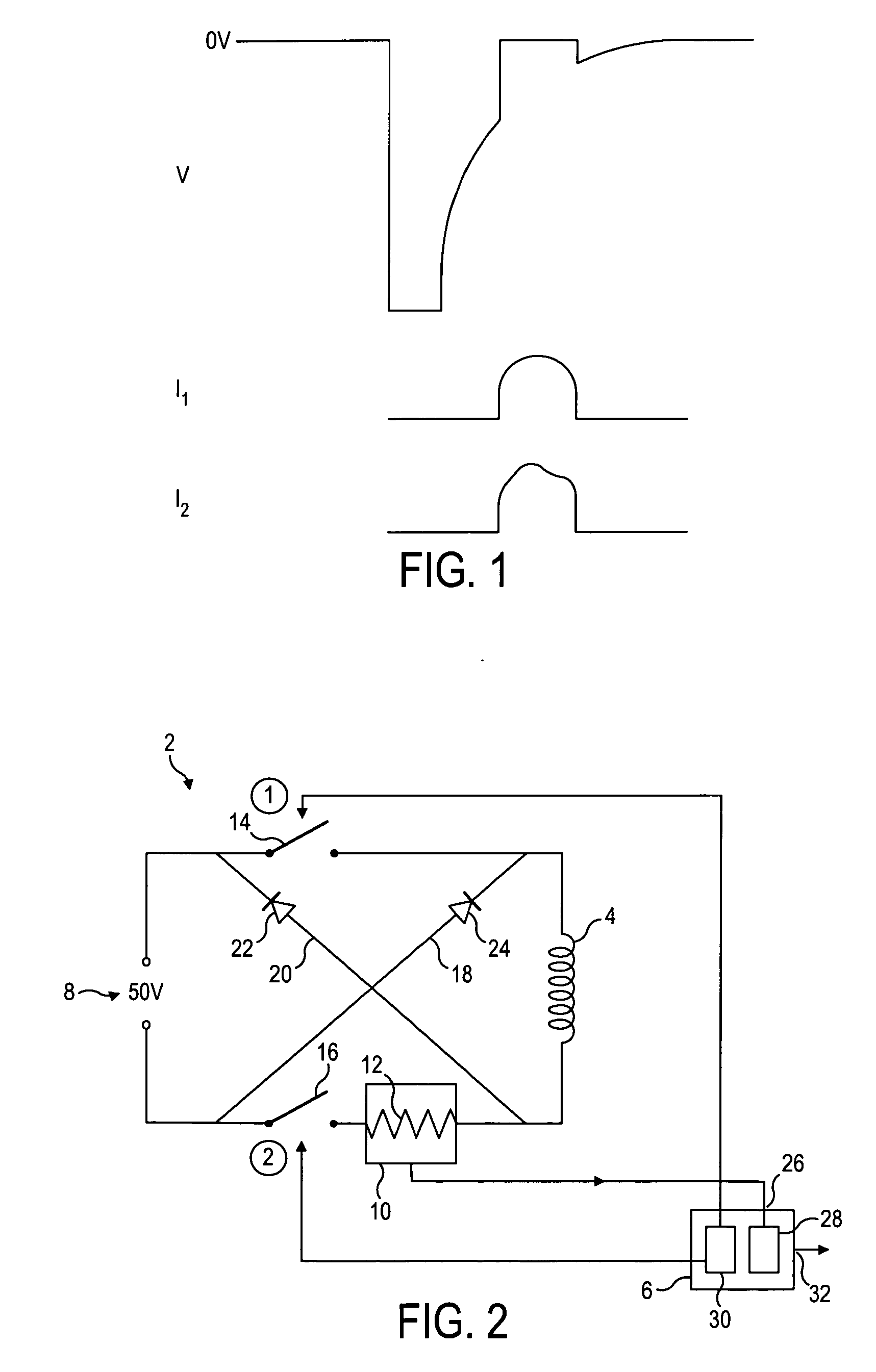
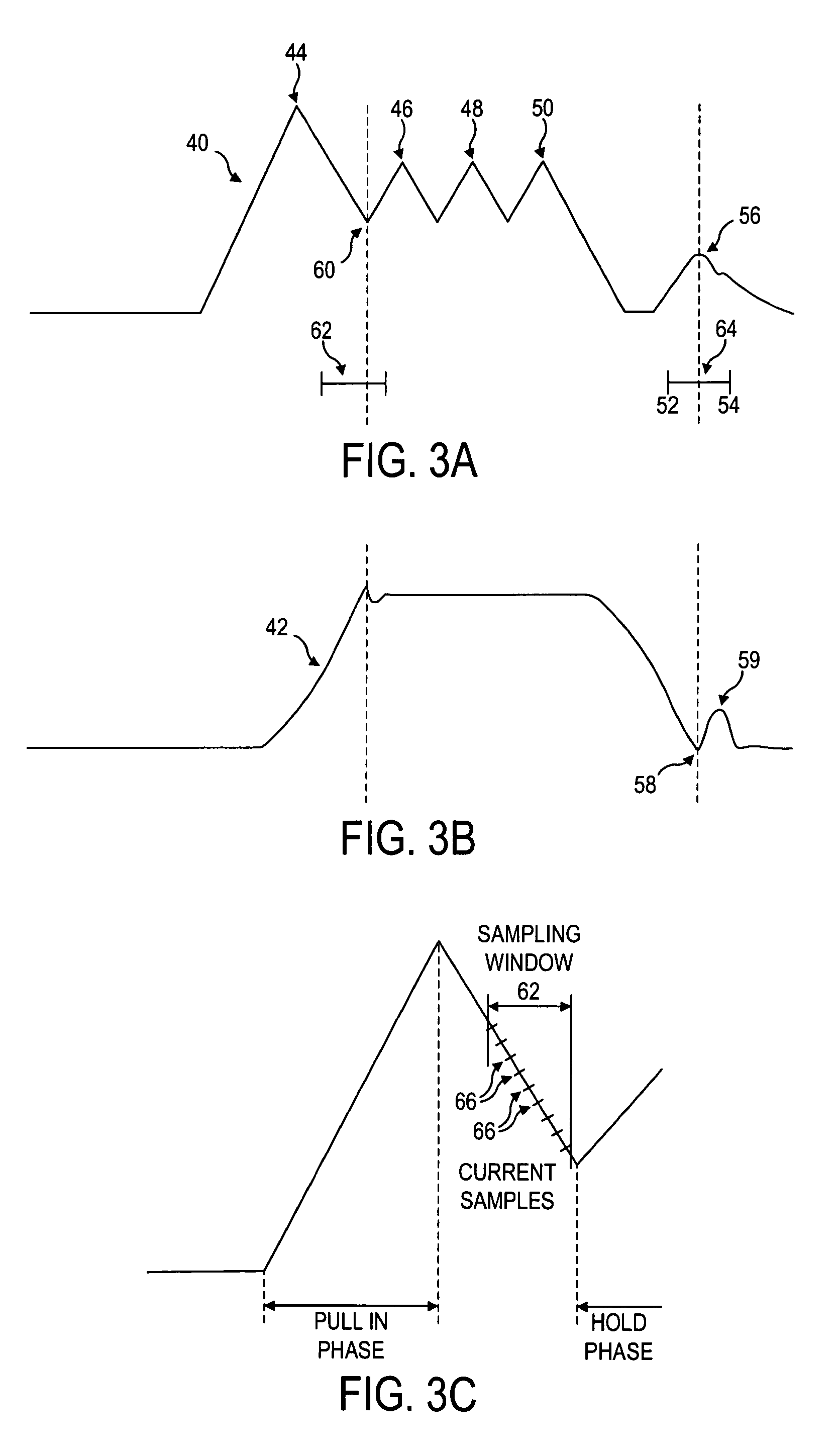
[0031]The processor is arranged to analyze the current through the actuator during the sampling window and to look for and identify discontinuities in the current flow. Such discontinuities can be linked to, for example, the valve reaching its stop and so the processor is effectively able to determine valve movements in dependence upon measured current discontinuities.
[0042]The second derivative may be determined based on a differential process, for which input data points are non-consecutive. This provides a processing advantage because a mathematical implementation based on a differential implementation is numerically one of the fastest operations that can be performed by a CPU.
[0043]The received data may be input to an analysis routine of the processor in the form of integer values having no units, thereby to minimize data handling and manipulation requirements.
[0044]Alternatively, the processor may be arranged to determine the presence of a current discontinuity if the second derivative of the current through the actuator exceeds a threshold value. This enables the detector to “filter out” transient effects within the current profile. For example, the second derivative of the current through the actuator should also exceed the threshold value for a set period of time in order for the detector to determine the presence of a current discontinuity. This also helps filter out transient spikes in the profile.

Problems solved by technology

As a consequence this means that factory limits during production must be tight and engine testing must be sensitive enough to pick up the performance of the injector(s).
However, no matter how good the initial set up, there will be a drift in performance over the life of the injector as components bed in or wear out.
It follows that one of the main disadvantages of the system without fault is that there is no way to control the injector timing to compensate for any changes that occur over the life of the system.
It is known that the injector components can undergo two significant changes after installation, namely the bedding in period and wear caused during normal operation.
There is currently no method to track changes in the valve movement characteristics in situ.
One of these limitations is that the fault / sampling window actually adds energy to the system (since a voltage is artificially applied so as to drive additional current into the system) and as such is influencing the system performance.
More specifically, the extra energy can extend the time the valve is actuated by adding enough energy to effectively re-actuate the valve or lead to erratic valve timing where the force / energy balance is close to sensitive limits.
Fault windows may also have the problem that the window position has an influence on the position of the current discontinuity that is recorded.
The closer the fault (“the discontinuity”) is to the end of the fault window, the more energy has entered the coil windings and as such this will tend to retard the natural progress of the valve (partial re-energization).
This means the greater the window length before the fault, the greater the magnitude of the imposed error.
Due to the operating environment of the injectors, there is typically a degree of electrical noise (typically high frequency RF) present in the engine system.
Existing methods for fault detection that include digital signal processing are either too slow (mathematically intensive) to avoid the error due to window position or they are insufficiently effective at eliminating noise induced errors.
A key difficulty in prior art fault detection systems is discriminating between a valid fault and a non valid event.
The difference between these two profiles can be subtle and traditionally has been difficult to determine mathematically for the wide range of different possible valve motions.
This is further complicated by the range of possible coil response profiles that all give slightly different current decay shapes.

Method used


Image

  • Fault detector and method of detecting faults
  • Fault detector and method of detecting faults
  • Fault detector and method of detecting faults

Examples


first embodiment

[0089]A sampling window and method of fault detection in accordance with the present invention is shown in FIG. 5. In this embodiment of the invention the sampling window is not fixed at a certain point in the combustion cycle of the engine but is instead capable of being swept in time between different cycles.

[0090]In FIG. 5, five different sampling window locations are depicted relating to a specific injection event (e.g. pre-injection, main injection or post injection) within subsequent injection cycles. It is also noted that the five sampling window locations are arranged to be progressively moved away from the end of the hold region in successive injection cycles. This is done in order to ensure that the first fault is detected and to mitigate against the possibility of a secondary fault (caused by valve bounce as described) above being misclassified as the primary fault.

[0091]The window 80 starts in an initial position (Position 1) that may be a fixed period of time after the ...

second embodiment

[0133]In the present invention an analysis technique for determining the presence of a discontinuity in the sampled current profile is disclosed.

[0134]It can be seen from FIGS. 4, 6-8 that the position of the maximum in the current profile moves with the sampling window 80 until a fault 112 is uncovered, at which point the current maximum remains fixed.

[0135]One method of analysis for determining the location of a fault is to record and plot the position (in time) of the current maximum. The location of a fault is determined by looking for “bunching” in the position of the current maximum, for example as the window is moved between successive positions (in different engine operating cycles) the temporal location of the current maximum is expected to change by a known amount. As the fault is approached the maximum will move relatively less (compared to readings taken before the sampling window reached the fault point) and so the measured current maximum positions will get closer to o...


PUM


Abstract

A fault detector for detecting valve movement of a valve in a fuel injector of an engine system, the valve comprising an electromagnetic actuator arranged to move the valve between first and second valve positions during a valve cycle, the engine system comprising a sensor for sensing a current through the actuator. The detector comprises a controller arranged to control the sensor; inputs for receiving from the sensor data related to the current through the actuator; a processor arranged to analyze the received data for current discontinuities; and outputs for outputting a valve movement signal in dependence upon the current discontinuities determined by the processor. The controller is arranged to enable the sensing means during a finite sampling window and to: (i) move the sampling window from a first window position for a first injection event to a progressively later window position for one or more subsequent injection events; (ii) to determine a new sampling window position on the basis of a valve movement signal output for at least two of the preceding window positions; and (iii) to feedback the new sampling window position for a subsequent injection event.

Description

TECHNICAL FIELD[0001]The present invention relates to a fault detector and method of detecting faults. More particularly, the present invention relates to the detection of valve movement of a valve in a fuel injector of an engine system via detection and analysis of discontinuities (“faults”) in the current through a control actuator of the valve.BACKGROUND TO THE INVENTION[0002]In electronically-controlled fuel injection systems, actuator controlled valves (e.g. solenoid valves) are used to control the flow of fuel within the injector, and hence, timing, pressure and quantity of fuel injected into the engine cylinders.[0003]For single-valve injection systems, such as Electronic Unit Injectors (EUIs) and Electronic Unit Pumps (EUPs) a single solenoid valve—known as the “Spill Valve”—is used to control the point, or set of conditions, at which fuel pressure within the injector volume begins to increase. If the valve is open, fuel will be allowed to “spill” to low pressure (the fuel t...

Claims


Application Information

Patent Timeline
IPC IPC(8): G01B5/28
CPCF02D41/20F02D2041/2055F02D2041/2058H01F2007/1888H01F2007/1855H01F2007/1866F02D2250/14F02D41/402
Inventor PEARCE, DANIEL A.HARCOMBE, ANTHONY THOMAS
Owner DELPHI TECH IP LTD
Learn More