
High power zoom lens system and image pickup apparatus

Active Publication Date: 2009-05-21
FUJI PHOTO OPTICAL CO LTD
View PDF3 Cites 13 Cited by
  • Summary
  • Abstract
  • Description
  • Claims
  • Application Information

AI Technical Summary

Benefits of technology

[0010]In the configuration having the five groups, the high power zoom lens system according to the aspect of the invention employs a so-called floating mode for relatively moving the third lens group and the fourth lens group. Thus, it is possible to satisfactorily correct image plane variation during zooming and satisfactorily suppress variation of spherical aberration and comatic aberration during zooming. In addition, by providing an aspheric lens having a high aberration correction performance to the fourth lens group used for the floating mode, it is possible to effectively suppress occurrence and variation of various aberrations. In this manner, according to the high power zoom lens system of the aspect of the invention, it is possible to embody a zoom lens system capable of achieving miniaturization with a high zoom ratio and suppressing variation of spherical aberration and comatic aberration during zooming.
[0018]According to the aspects of the invention, the zoom lens system is configured to have at least five groups. In the lens system, the configurations of the lens groups are appropriately set. In particular, the third lens group and the fourth lens group are operable to be movable relative to each other during zooming, and the fourth lens group is configured to have the aspheric lens. Thus, it is possible to provide a high power zoom lens system capable of achieving high power without increasing a total length of the optical system and maintaining excellent optical performance by suppressing variation of spherical aberration and comatic aberration during zooming. In addition, it is also possible to provide an image pickup apparatus having the high power zoom lens system.

Problems solved by technology

However, as magnifying power increases, aberration variation accompanied by zooming remarkably deteriorates.
Thus, it is hard to achieve a high power while satisfying a constraint condition of the total length of the optical system.
In addition, it is also hard to obtain high optical performance in the entire range of zooming by suppressing aberration variation accompanied by zooming.

Method used


Image

  • High power zoom lens system and image pickup apparatus
  • High power zoom lens system and image pickup apparatus
  • High power zoom lens system and image pickup apparatus

Examples


example 1

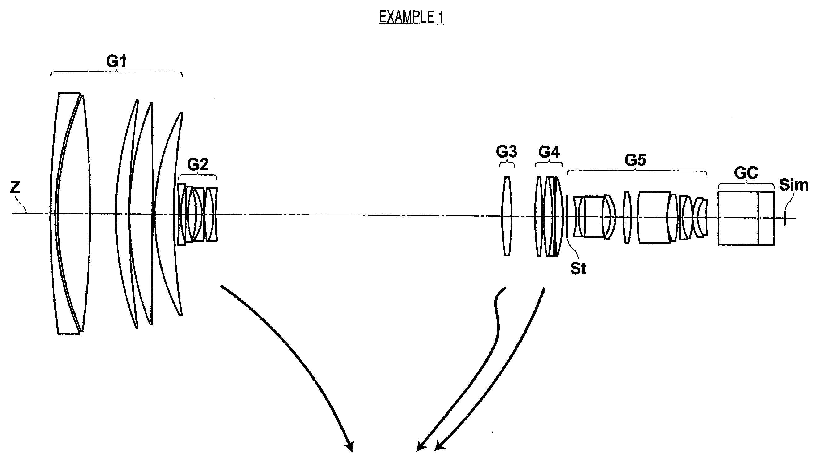
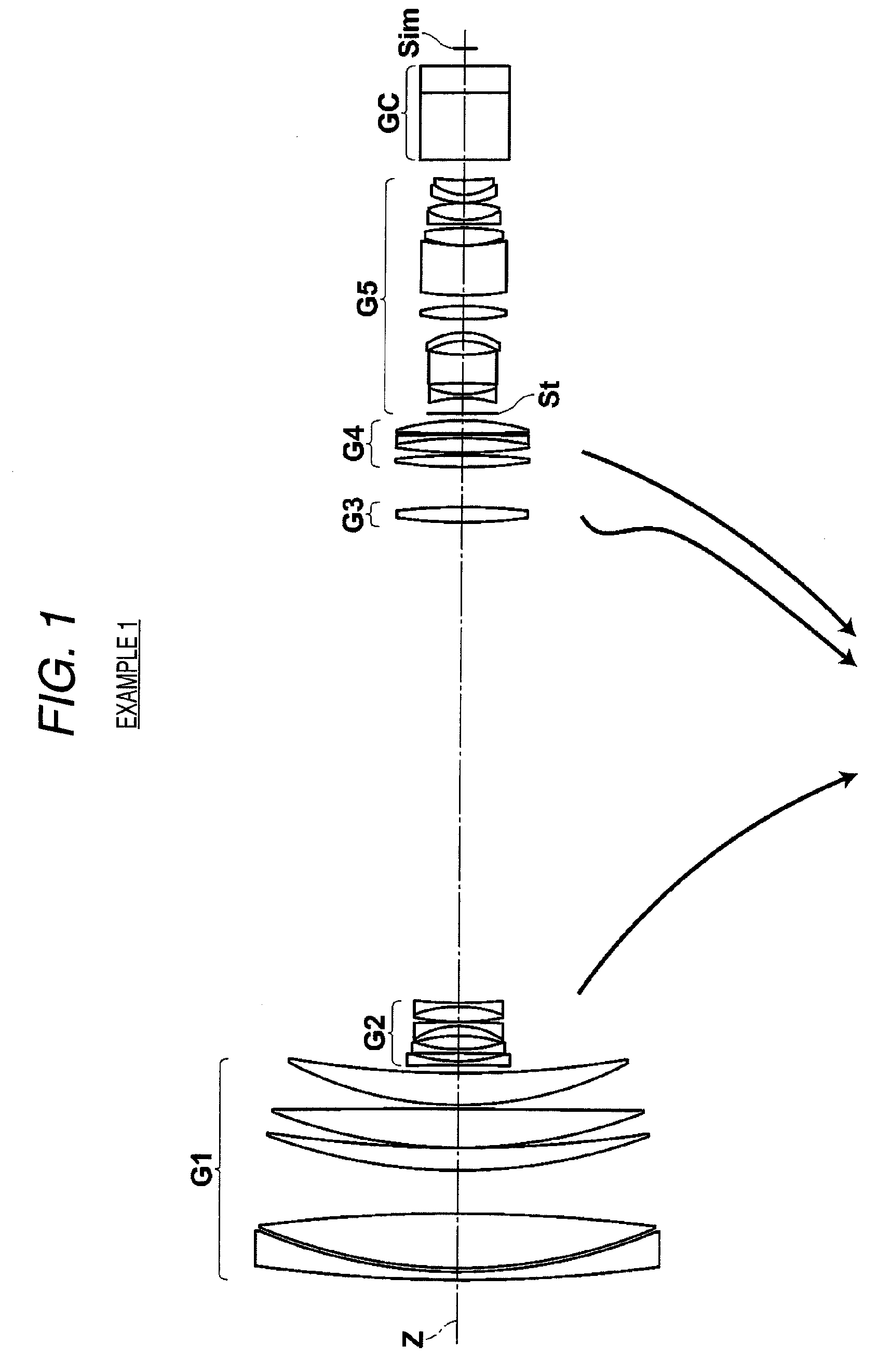
[0104]A lens sectional diagram of Example 1 is shown in FIG. 1, and the detailed configuration is shown in FIGS. 8A to 8C. FIG. 8A shows a detailed configuration of the first lens group G1 and the second lens group G2. FIG. 8B shows a detailed configuration of the third lens group G3 and the fourth lens group G4. FIG. 8C shows a detailed configuration from the fifth lens group G5 to the imaging plane Sim.

[0105]In Example 1, the first lens group G1 has a five-lens configuration of lenses L1 to L5, the second lens group G2 has a six-lens configuration of lenses L21 to L26, the third lens group G3 has an one-lens configuration of a lens L31, the fourth lens group has a four-lens configuration of lenses L41 to L44, and the fifth lens group G5 has an eleven-lens configuration of lenses L51 to L61 and an aperture diaphragm St.

[0106]The surface data of the high power zoom lens system according to Example 1 is represented in Table 1. The various data thereof is represented in Table 2. The a...

example 2

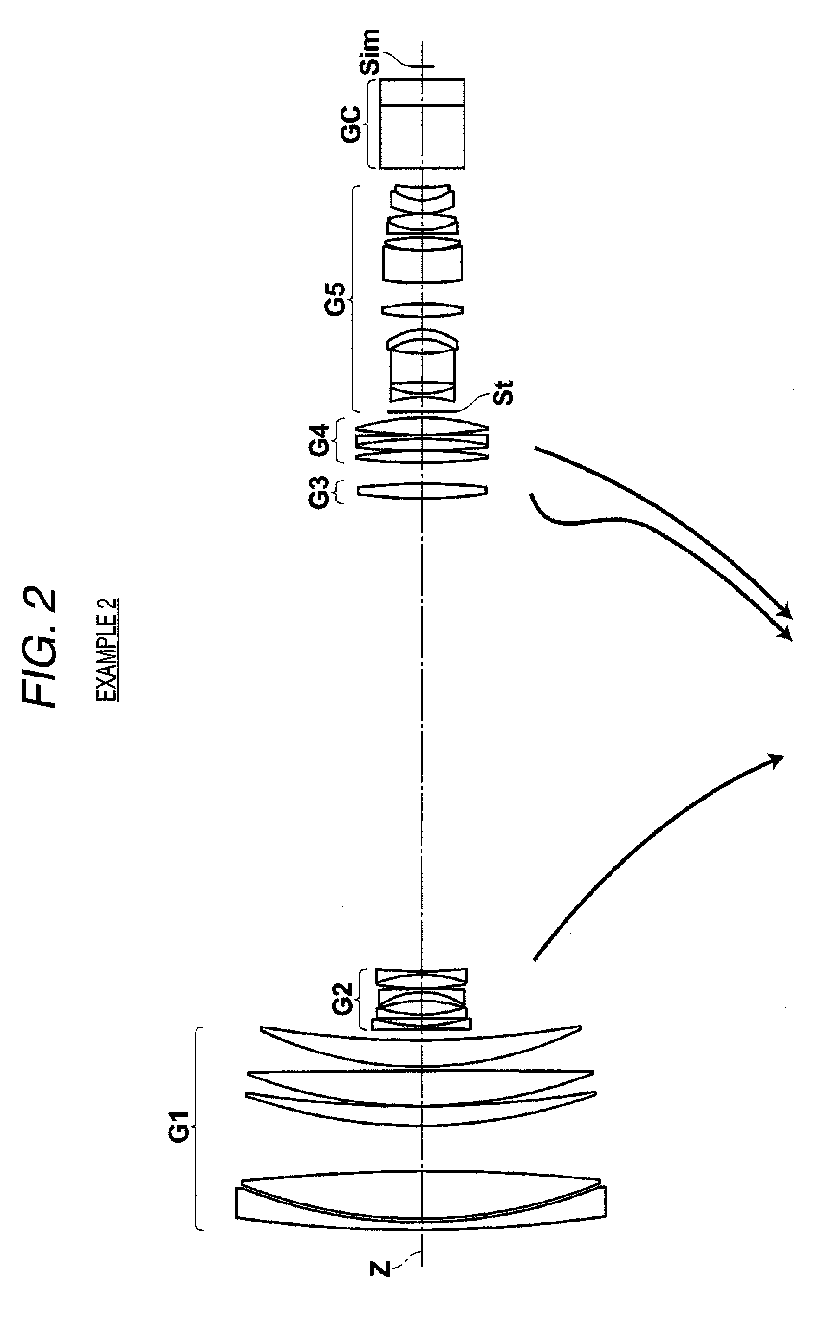
[0111]A lens sectional diagram of Example 2 is shown in FIG. 2, and the detailed configuration is shown in FIGS. 9A to 9C. FIG. 9A shows a detailed configuration of the first lens group G1 and the second lens group G2. FIG. 9B shows a detailed configuration of the third lens group G3 and the fourth lens group G4. FIG. 9C shows a detailed configuration from the fifth lens group G5 to the imaging plane Sim.

[0112]In Example 2, the first lens group G1 has a five-lens configuration of lenses L1 to L5, the second lens group G2 has a six-lens configuration of lenses L21 to L26, the third lens group G3 has an one-lens configuration of a lens L31, the fourth lens group has a four-lens configuration of lenses L41 to L44, and the fifth lens group G5 has an eleven-lens configuration of lenses L51 to L61 and an aperture diaphragm St.

[0113]The surface data of the high power zoom lens system according to Example 2 is represented in Table 4. The various data thereof is represented in Table 5. The a...

example 3

[0116]A lens sectional diagram of Example 3 is shown in FIG. 3, and the detailed configuration is shown in FIGS. 10A to 10C. FIG. 10A shows a detailed configuration of the first lens group G1 and the second lens group G2. FIG. 10B shows a detailed configuration of the third lens group G3 and the fourth lens group G4. FIG. 10C shows a detailed configuration from the fifth lens group G5 to the imaging plane Sim.

[0117]In Example 3, the first lens group G1 has a five-lens configuration of lenses L1 to L5, the second lens group G2 has a six-lens configuration of lenses L21 to L26, the third lens group G3 has an one-lens configuration of a lens L31, the fourth lens group has a four-lens configuration of lenses L41 to L44, and the fifth lens group G5 has an eleven-lens configuration of lenses L51 to L61 and an aperture diaphragm St.

[0118]The surface data of the high power zoom lens system according to Example 3 is represented in Table 7. The various data thereof is represented in Table 8. ...


PUM


Abstract

A high power zoom lens system includes, in order from the object side: a first lens group having a positive refractive power and remaining stationary during zooming; a second lens group having a negative refractive power and moving during zooming; a third lens group and a fourth lens group having a positive refractive power and being movable relative to each other to correct image plane variation accompanied by zooming; and a fifth lens group having a positive refractive power and including an aperture diaphragm, the fifth lens group being used for forming an image. The second lens group and a composite lens group formed by combining the third lens group and the fourth lens group pass simultaneously through −1×magnification points of the groups during zooming from a wide-angle end to a telephoto end. The fourth lens group has at least one aspheric surface.

Description

CROSS-REFERENCE TO RELATED APPLICATIONS[0001]This application is based on and claims priority under 35 USC 119 from Japanese Patent Application No. 2007-301645 filed Nov. 21, 2007; the entire of which are incorporated herein by reference.BACKGROUND[0002]1. Technical Field[0003]The present invention relates to a high power zoom lens system and an image pickup apparatus, and more particularly to a high power zoom lens system suitable for being mounted on a television camera, a video camera, and the like and an image pickup apparatus having the high power zoom lens system.[0004]2. Related Art[0005]Generally, as zoom lens systems mounted on a television camera, a video camera, and the like, zoom lens systems formed of four groups have been known. An exemplary zoom lens system formed of four groups includes in order from an object side: a first lens group having a positive refractive power; a second lens group having a negative refractive power and serving as a zooming group movable for ...

Claims


Application Information

Patent Timeline
IPC IPC(8): G02B15/15
CPCG02B15/173G02B15/145129
Inventor TOYAMA, NOBUAKI
Owner FUJI PHOTO OPTICAL CO LTD
Learn More