
Optical imaging system with extended depth of focus

a technology of optical imaging and depth of focus, applied in the field of optical imaging systems, can solve the problem that the intensity of the central peak is expected to vary only slowly

Inactive Publication Date: 2009-05-21
ECOLE POLYTECHNIQUE FEDERALE DE LAUSANNE (EPFL)
View PDF4 Cites 25 Cited by
  • Summary
  • Abstract
  • Description
  • Claims
  • Application Information

AI Technical Summary

Benefits of technology

The patent describes an imaging apparatus and method for producing a high-quality image of a sample using Optical Coherence Tomography (OCT). The apparatus includes a light source, sample holding means, an interferometer, reference means, and an objective. The apparatus can produce a ring-shaped or multi-spot light source in the front focal plane or any conjugated plane of the objective. The depth information can be obtained by detecting the resulting spectral interference pattern at the exit of the interferometer. The technical effects of this patent include improved image quality, faster imaging speeds, and better sensitivity for in-vivo imaging of biological tissue.

Problems solved by technology

Secondly, the intensity of the central peak is expected to vary only slowly within the range of intersection.

Method used


Image

  • Optical imaging system with extended depth of focus
  • Optical imaging system with extended depth of focus
  • Optical imaging system with extended depth of focus

Examples


Embodiment Construction

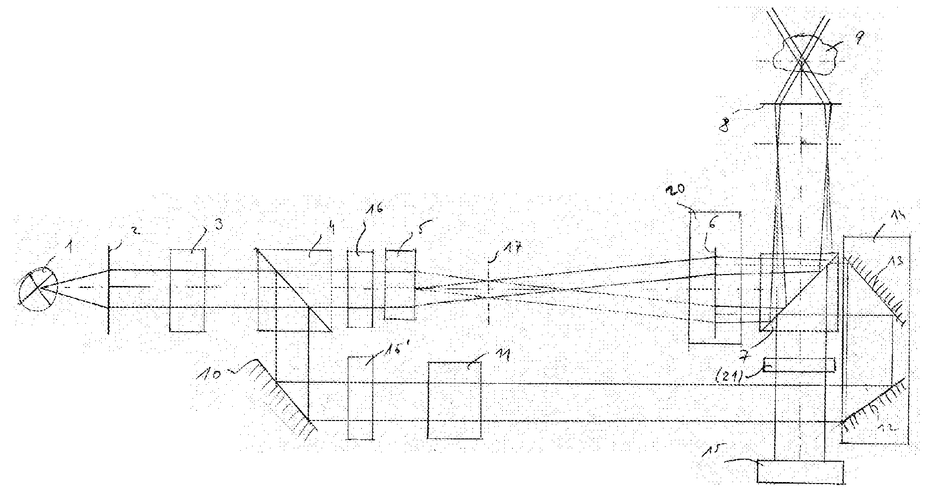
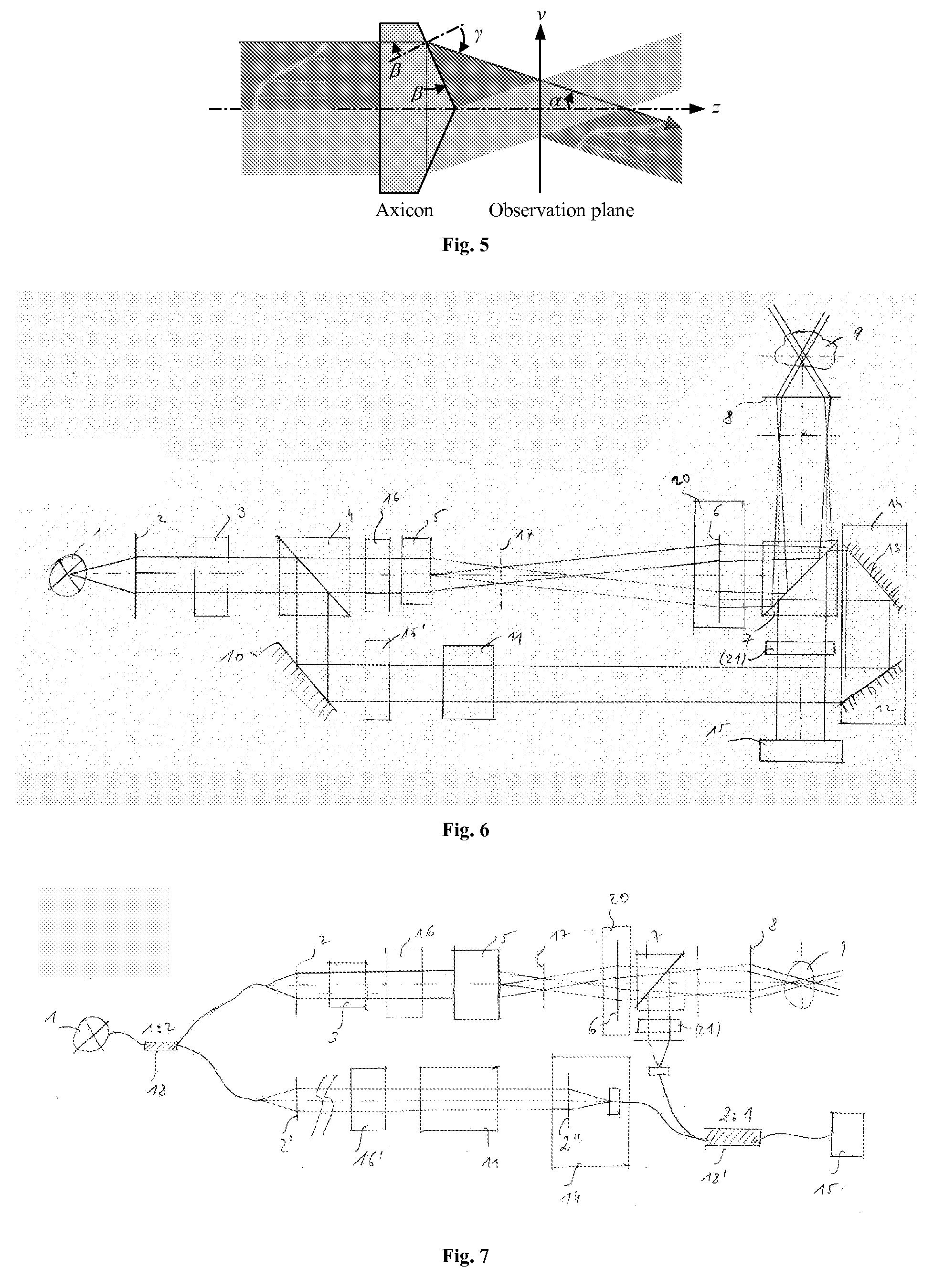
[0039]As it can be seen on the embodiment of FIG. 6, the apparatus comprises the following elements: (1) source; (2) collimator optics; (3) polarization control; (4) beam splitting means; (5) wavefront manipulator (e.g. axicon, prism, DMD, SLM, but limited to those); (6) lens; (7) beam splitting means; (8) objective; (9) sample; (10) reflector; (11) dispersion control; (12) and (13) reflector; (14) reference delay control (e.g. translation stage); (15) detector; (16) and (16′) phase modulation means or frequency shifting means; (17) focal plane with Bessel beam intensity pattern; (20) (instead of (6)) relay optics to access the conjugate plane to the front focal of the objective (8) and to position at this place e.g. a beam steering unit (see FIG. 8); (21) optional negative mask ideally designed to block the intensity distribution in the front focal plane of the objective for true dark field detection; can also be designed to block different parts of the light backscattered from the...


PUM

PropertyMeasurementUnit
diameteraaaaaaaaaa
diameteraaaaaaaaaa
diameteraaaaaaaaaa

Abstract

The invention concerns an optical imaging apparatus comprising (o) a light source (1), (p) sample holding means, (q) an interferometer, (r) reference means, (s) an objective (8) which is adapted to have its sample side focal plane crossing a sample held in said sample holding means, (t) optical or electro-optical means (2, 3, 5, 16) adapted to produce a ring shaped or multi-spot light source in the front focal plane (17) or any conjugated plane (17′) of said objective (8), at least one detector. The invention also includes a method for using said apparatus where the sample is illuminated by an interference pattern and the depth information is obtained by using optical Coherence Tomography.

Description

FIELD OF INVENTION[0001]The invention relates to optical imaging systems and more precisely to such systems and related methods using Optical Coherence Tomography (OCT).STATE OF THE ART[0002]Several high-resolution systems are already existing in optical imaging, e.g. in microscopy.[0003]Optical Coherence Tomography (OCT) is a high speed imaging technique that has been applied to measure full 3D tissue volumes in-vivo. In OCT the depth and transverse resolution are decoupled. The depth resolution is given by the coherence length of the employed light source, which in turn is proportional to the spectral width, while the transverse resolution is determined by the numerical aperture (A) of the objective. The detection in depth however has the drawback of losing transverse resolution along the optical axis especially if high numeric aperture objectives are used.[0004]The axial resolution in OCT is given by the round trip coherence length and is defined as lc=2 ln(2)λ02 / πΔλ, where lc is...

Claims


Application Information

Patent Timeline
Patent Type & Authority Applications(United States)
IPC IPC(8): G01N21/47
CPCG01N21/4795G01B9/02044G01B2290/70G01B9/02002G01B9/02091G01B9/02035
Inventor LEITGEB, RAINERLASSER, THEOBACHMANN, ADRIANSTEINMANN, LUKASVILLIGER, MARTIN
Owner ECOLE POLYTECHNIQUE FEDERALE DE LAUSANNE (EPFL)
Learn More