
Power Steering Apparatus

a technology of power steering and motor shaft, which is applied in the direction of steering initiation, instruments, vessel construction, etc., can solve the problems of motor torque being added to the steering shaft, delay in control, and unintended assist force being generated by motor inertia, so as to reduce unnatural feeling and avoid unintended effects

Inactive Publication Date: 2009-05-14
HITACHI LTD
View PDF3 Cites 5 Cited by
  • Summary
  • Abstract
  • Description
  • Claims
  • Application Information

AI Technical Summary

Benefits of technology

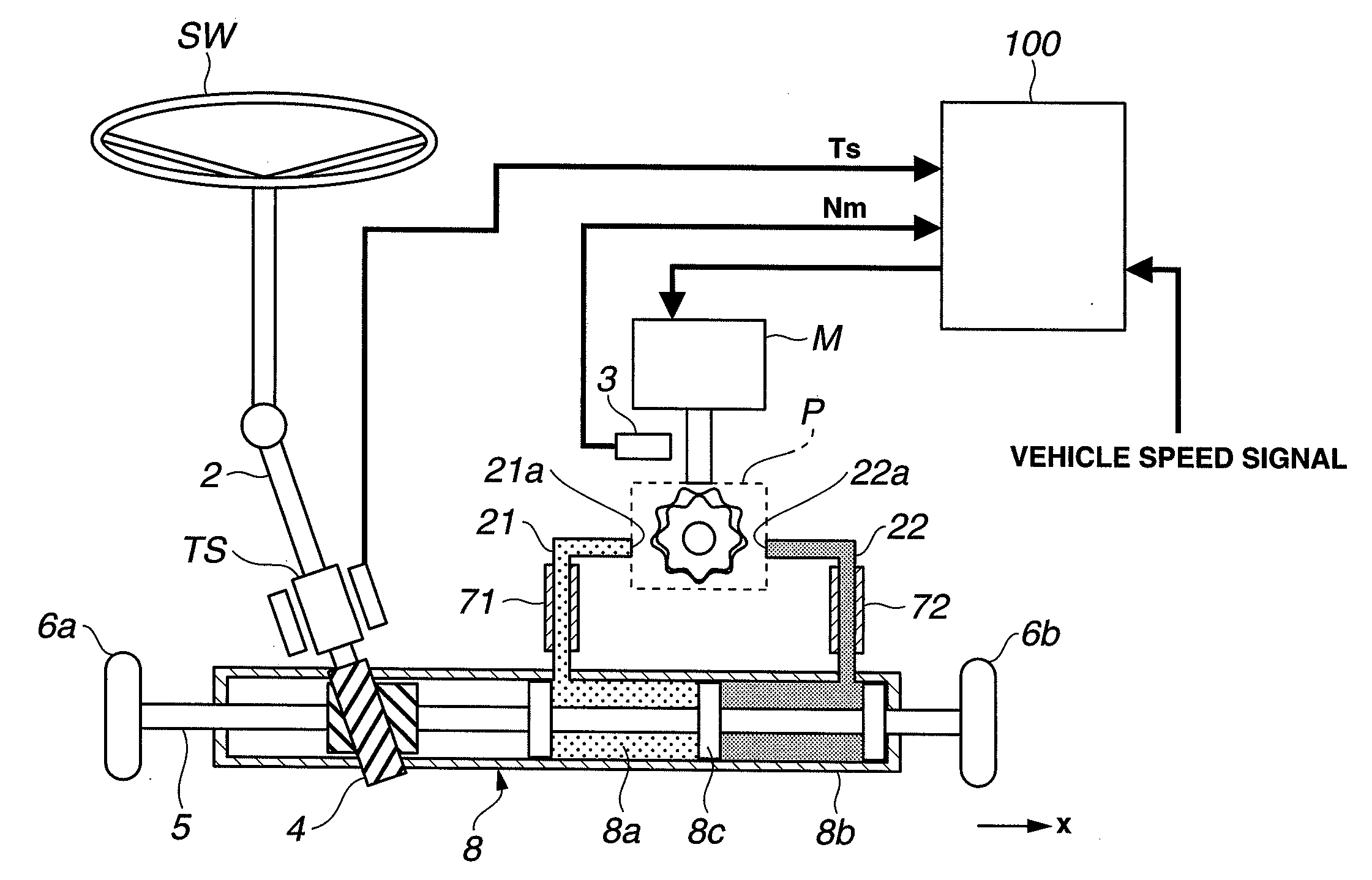
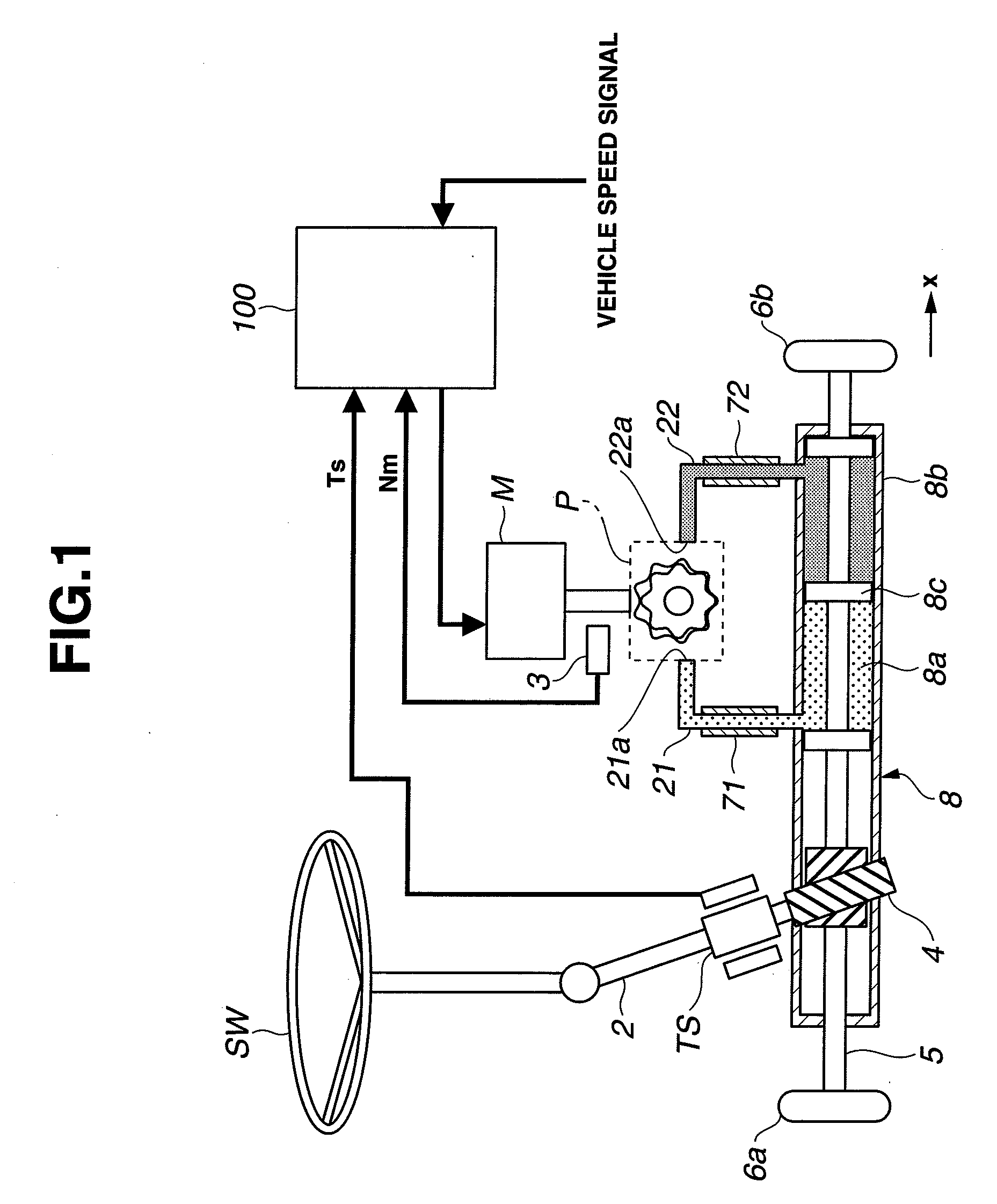
[0006]It is, therefore, an object of the present invention to provide a power steering apparatus devised to solve the above mentioned problem, to avoid an unintended movement (hunting) of a steering wheel in a hand free state, and to decrease an unnatural feeling.

Problems solved by technology

However, in the above-described power steering apparatus, a motor torque may be added to a steering shaft by an inertia and a delay of a control even when a steering assist command is finished.
In case of an electric power steering apparatus which directly drives a rack shaft by a motor, an unintended assist force may be generated by the motor inertia and the response delay of the control even when the hands of the driver are released from the steering wheel (in a hand free state).

Method used


Image

  • Power Steering Apparatus
  • Power Steering Apparatus
  • Power Steering Apparatus

Examples


second embodiment

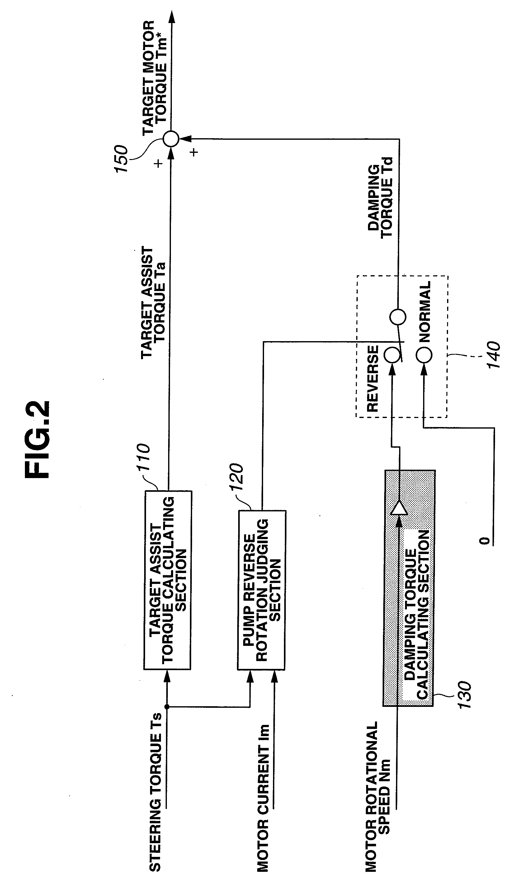
[0080]Hereinafter, a second embodiment will be illustrated. The basic structure of the second embodiment is identical to the structure of the first embodiment. In the first embodiment, the normal / reverse rotation of pump P is judged based on the direction of the current of motor M and the steering torque direction. In this second embodiment, the pump reverse rotation is determined when the sign of the steering torque sensed by torque sensor TS is different from the sign of the variation of this steering torque.

[0081]FIG. 20 is a control block diagram showing control unit 100 in the second embodiment. Pump reverse rotation judging section 120 includes a torque direction (sign) judging section 121, a torque variation direction (sign) judging section 122, and a sign judging section 123. Pump reverse rotation judging section 120 is configured to judge accord or disaccord between the sign of the inputted steering torque Ts and the sign of the differential value of the inputted steering t...

fourth embodiment

[0092]Hereinafter, a fourth embodiment will be illustrated. In the fourth embodiment, the pump reverse rotation is judged by comparison of the steered direction of steered wheels 6a and 6b and the pressures of first and second cylinders 8a and 8b. FIG. 23 is a control block diagram in the fourth embodiment. Steered direction judging section 127 judges the steered direction based on the movement speed of rack shaft 5. Direction judging section 123a judges the accord or the disaccord by comparison between the assist direction and the steered direction to determine the provision / non-provision of damping torque Td.

[0093]In the power steering apparatus according to the embodiment of the present invention, the pump reverse rotation judging section is configured to judge the reverse rotation state of the reversible pump by comparing a steered direction of the steered wheels and the hydraulic pressure generated in the power cylinder. Accordingly, it is possible to further improve the steeri...


PUM


Abstract

A power steering apparatus includes: a steering mechanism connected with a steering wheel; a transmitting mechanism connecting the steering mechanism and a steered wheels; a motor arranged to drive the transmitting mechanism based on a torque inputted to the steering mechanism to provide a steering assist force to the steered wheels; a motor control section configured to output a drive signal to the motor in accordance with the steering assist force; a motor reverse rotation judging section configured to judge a reverse rotation state of the motor when an actual rotation direction of the motor does not correspond to a direction in which the motor is rotated by the driving signal from the motor control section; and a damping torque adding section configured to damp a torque generated in the motor when the motor reverse rotation judging section determines the reverse rotation state of the motor.

Description

BACKGROUND OF THE INVENTION[0001]This invention relates to a power steering apparatus arranged to assist a steering of a driver.[0002]Japanese Patent Application Publication No. 2006-131074 shows a power steering apparatus arranged to drive a rack shaft by a motor to provide a steering assist force.SUMMARY OF THE INVENTION[0003]However, in the above-described power steering apparatus, a motor torque may be added to a steering shaft by an inertia and a delay of a control even when a steering assist command is finished. Consequently, the steering wheel may be moved unlike a driver's intention.[0004]In case of an electric power steering apparatus which directly drives a rack shaft by a motor, an unintended assist force may be generated by the motor inertia and the response delay of the control even when the hands of the driver are released from the steering wheel (in a hand free state). This unintended assist force may rotate the steering wheel.[0005]In case of a hydraulic power steeri...

Claims


Application Information

Patent Timeline
Patent Type & Authority Applications(United States)
IPC IPC(8): B62D6/10
CPCB62D5/065B62D5/0466
Inventor MATSUMURA, TATSUOSASAKI, MITSUOTAKAHASHI, TORU
Owner HITACHI LTD
Learn More