
High Water-Speed Tracked Amphibian

Active Publication Date: 2009-05-14
FAST TRACK AMPHIBIAN
View PDF19 Cites 17 Cited by
  • Summary
  • Abstract
  • Description
  • Claims
  • Application Information

AI Technical Summary

Benefits of technology

[0005]The tracked amphibian of this invention uses the tracks as the sole means of propulsion for high speed on the water as well as on the land. This feature has the benefit of eliminating the complexity, weight and maintenance of a dual propulsion system. As demonstrated by snowmobiles that can run at high speed (over 80 mph) on the water, propulsion by tracks is very efficient. In fact, the higher the speed the more efficient the tracks become, and they also eliminate hull drag by providing some or all of the lift. The propulsive efficiency of the tracks is given by the ratio of vehicle speed to track speed: Eff=speed of the vehicle / speed of the track (100). For instance a test bed at the speed of 39 mph with a track speed of 48 mph has demonstrated a propulsive efficiency of: Eff=39 / 48(100)=81%. At 60 mph, efficiency would be even higher (approximately 90%).
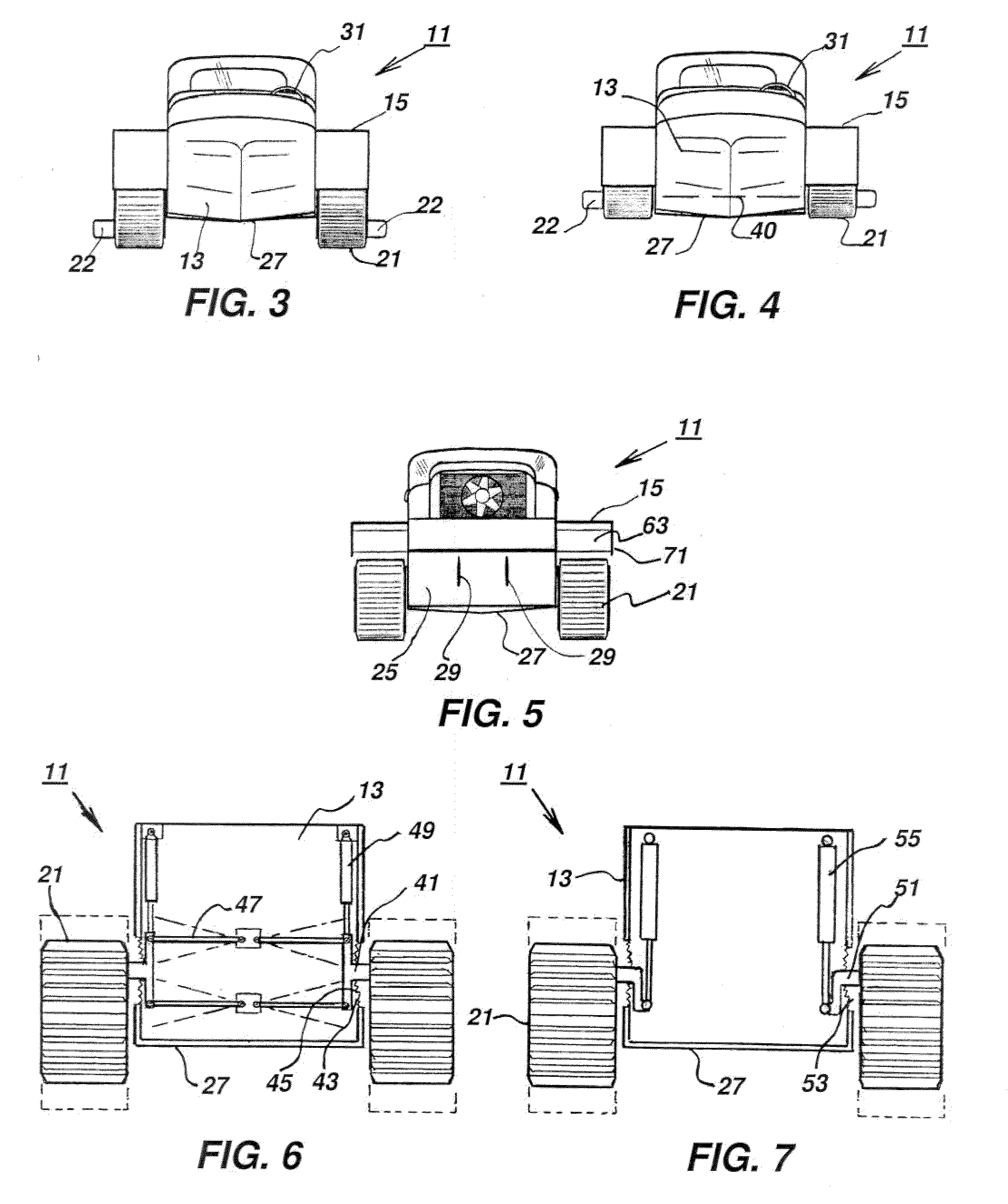
[0011]In this invention the vehicle body or hull is made similar to a boat with a flat or “V” bottom and, in a preferred embodiment, with a step aft of the center of gravity. The track assemblies are positioned as close as possible to the sides of the hull and permitted to move up and down either by swing arms or torsion bars. Vertical travel of the track assemblies is controlled by shock absorbers mounted fore and aft to minimize the jar when passing over bumps on the land and waves in the water. Preferably the steady vertical position of the tracks can be positioned full up or full down or positions in between by specially designed air shock absorbers and air cylinders that use air to push the tracks down or to pull the tracks up. This flexibility permits maximum obstacle clearance on the land and optimizes the relative vertical positioning of the tracks to the hull for optimizing low speed performance or high speed performance or the best wave impact attenuation on the water. Raising or lowering the tracks could also be accomplished with actuation means in a series connection with conventional shock absorbers and springs.
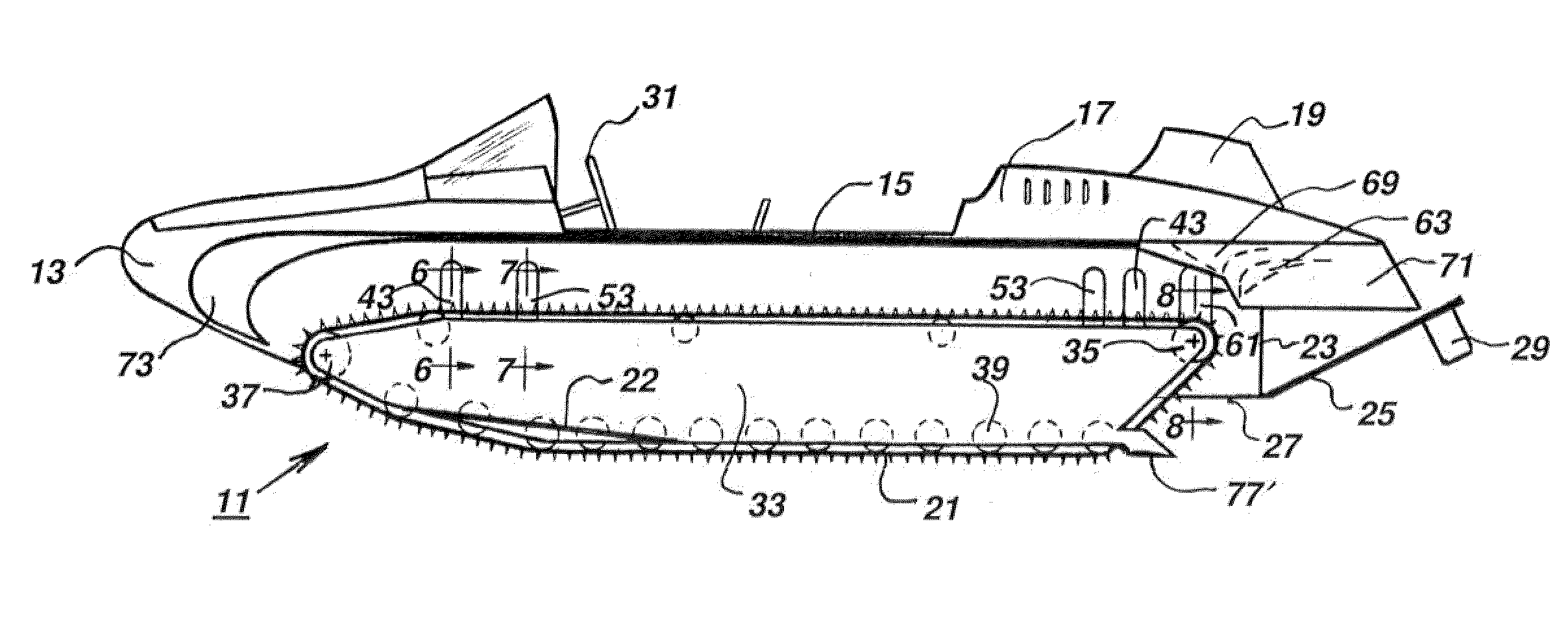
[0013]Devices and appendages can be used individually or collectively to overcome the re-circulation of water and loss of thrust in the water when at low speed or at a stand still. A preferred embodiment includes diverter vanes at the aft end near the top of the tracks to direct the water aft when going forward and at the front of the tracks to direct the water forward when backing up. A transom flap can be positioned to optimize hull lift and trim on the water. The transom flap can be raised for obstacle clearance on the land. Cavitation plates behind the tracks can be used to help when starting on the water with the tracks full down, but they would have to be retracted for obstacle clearance when backing on land.
[0014]For simplicity of operation, the vertical position of the tracks can be set in one position and left for operation in the water. Full up position gives the best performance, except at high speeds on the water where full down would lift the hull completely out of the water. The full down position with the tracks would also give the best mitigation of wave impact. Pulling the tracks full up is optimum for starting on the water.

Problems solved by technology

Those vehicles usually used propellers to help the tracks and wheels on the water and were very slow, with water-speeds less than 10 mph.
At the end of the 20th century there were still no operational military vehicles that could better the 10 mph water-speed.
However, a snowmobile cannot slow down below planing speed or it will sink and it cannot start or stop in the water.
Large ships can operate at high speeds without planning because of their large size and the hydrodynamic scaling effects.
Small boats, however, can only achieve high speeds efficiently by planing.
The dual propulsion system of tracks and water jets increases the complexity, cost, weight and maintenance.
Here again they have added complexity because of the dual propulsion system of wheels and water jets, and the wheels, of course, do not provide the all terrain capability of tracks for operating in deep mud, snow, sand, ice, and marshes.

Method used


Image

  • High Water-Speed Tracked Amphibian
  • High Water-Speed Tracked Amphibian
  • High Water-Speed Tracked Amphibian

Examples


Embodiment Construction

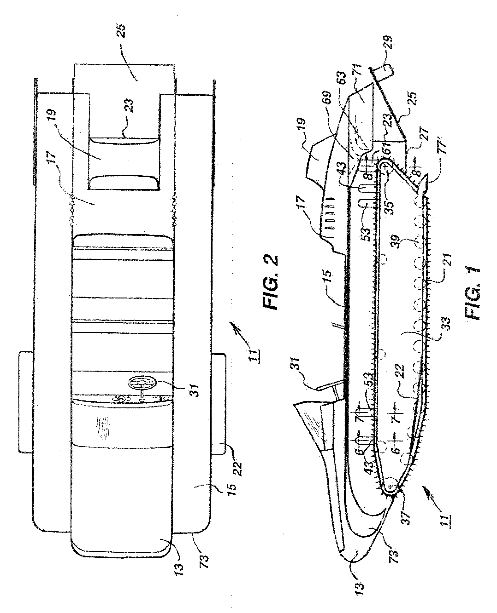
[0041]Referring to FIG. 1, vehicle 11 has a buoyant hull 13. In this embodiment, fenders 15 are mounted to hull 13 on each side. An engine is located in the aft portion of hull 13 and enclosed by an engine cowling 17. A radiator air scoop 19 serves as an air intake for cooling the radiator of the engine.

[0042]A continuous rotatable track 21 is mounted to each side of hull 13. Tracks 21 provide propulsion for hull 13 not only on land but also when water borne. A side splash plate 22 may be mounted to an outboard side of each track 21 for restricting water spray while under high forward speed in water. Splash plates 22 are located forward of the mid point along the length of vehicle 11.

[0043]Hull 13 has a transom 23, which is generally perpendicular to fenders 15 in this embodiment. A transom flap 25 is mounted by a hinge to the bottom of transom 23. Transom flap 25 extends rearward from transom 23. Transom flap 25 has a storage position inclined upward as shown in FIG. 15, and an ope...


PUM


Abstract

An amphibious vehicle capable of high speeds on the water has a buoyant hull with driven tracks on each side of the hull. The tracks are movable between an upper position and a lower position relative to the hull. The tracks propel the vehicle both for land travel and water travel. Water diverter vanes at the aft end of each track divert water being carried forward by the tracks. Water diverter vanes at the forward ends direct water carried on the upper runs in a downward and aft direction. A cavitation plate is located behind each of the tracks while waterborne and below the waterline of the hull. A tiltable transom flap is attached to the transom and extends rearward.

Description

FIELD OF THE INVENTION[0001]This invention related in general to an amphibious vehicle that uses tracks for propulsive force on the water as well as land and provides the potential for operating on the water at high speeds by planing on the water using hydrodynamic (in lieu of buoyancy) lift from the tracks and / or hull to support the weight of the vehicle.BACKGROUND OF THE INVENTION[0002]Tracked amphibian vehicles were developed prior to World War II and saw much use in the Pacific Theater as an amphibious assault craft that could go ashore and operate on land. Wheeled amphibians such as the “Duck” were also employed in WW II. Those vehicles usually used propellers to help the tracks and wheels on the water and were very slow, with water-speeds less than 10 mph. At the end of the 20th century there were still no operational military vehicles that could better the 10 mph water-speed. Snowmobiles with their rubber tracks had been running over the water at high speeds for over 25 years...

Claims


Application Information

Patent Timeline
IPC IPC(8): B60F3/00B63B1/00B62D55/084B62D11/08F16F9/02B62D55/10B63H25/38
CPCB60F3/0007B60F3/0015B63H1/34B60F2301/02B60F3/0038
Inventor WERNICKE, KENNETH G.WERNICKE, RODNEY K.WERNICKE, KEITH H.WERNICKE, TIMOTHY K.
Owner FAST TRACK AMPHIBIAN
Learn More