
Camera mounting structure, camera mounting method and exterior panel component of a vehicle

a technology for mounting structures and cameras, applied in television systems, instruments, printing, etc., can solve the problems that the related art camera mounting structure has not necessarily dealt with the increased demand for mounting appropriately and flexibly, and achieve the effect of reducing the number of vehicles

Active Publication Date: 2009-05-14
SONY CORP
View PDF2 Cites 56 Cited by
  • Summary
  • Abstract
  • Description
  • Claims
  • Application Information

AI Technical Summary

Benefits of technology

[0006]Recently, an on-vehicle camera has become widespread, and with this, demand for mounting the same has been drastically increased.
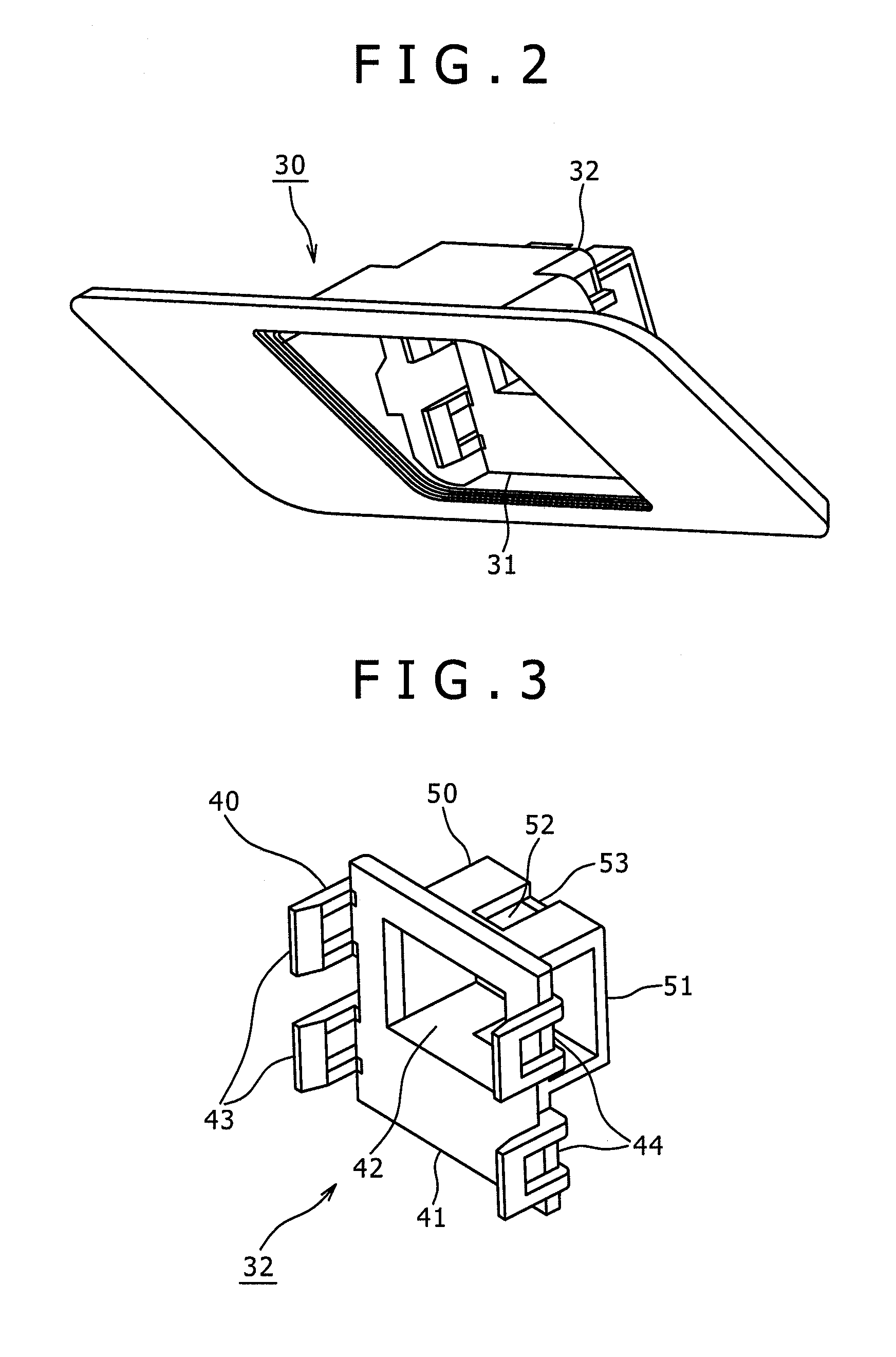
[0014]According to an embodiment of the present invention, since the preparation of the exterior panel component with which the bracket part is molded integrally allows the mounting of the on-vehicle camera to the vehicle without requiring any additional attaching member or the like, redundant work (e.g., component design, manufacturing, management and the like for each vehicle type) between the camera manufacturing side, and the vehicle manufacturing side and the like is not required, so as compared with the case where the redundant work is required, working efficiency is largely improved. In addition, versatility assurance in supporting each vehicle type becomes easy. Accordingly, the increased demand for mounting the on-vehicle camera can be dealt with appropriately and flexibly.

Problems solved by technology

Therefore, the related art camera mounting structure has not necessarily dealt with the increased demand for mounting appropriately and flexibly for reasons as described below.

Method used


Image

  • Camera mounting structure, camera mounting method and exterior panel component of a vehicle
  • Camera mounting structure, camera mounting method and exterior panel component of a vehicle
  • Camera mounting structure, camera mounting method and exterior panel component of a vehicle

Examples


Embodiment Construction

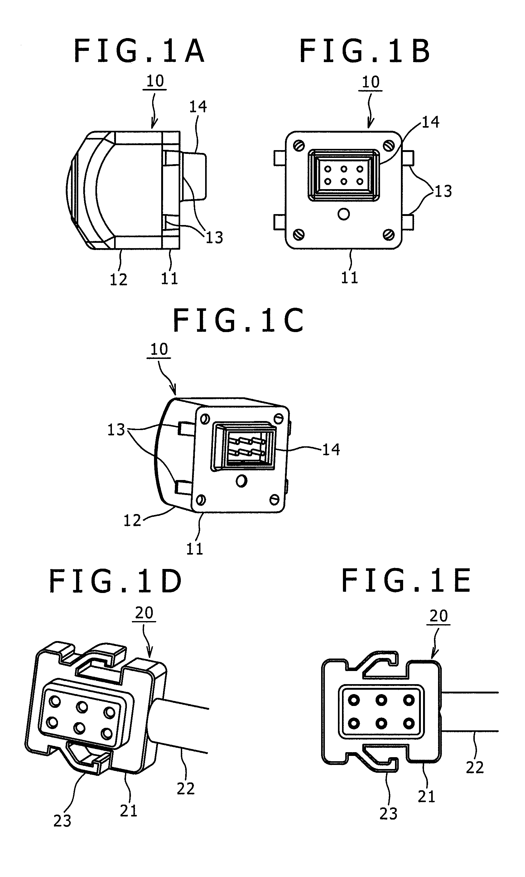
[0034]Hereinafter, a camera mounting structure, a camera mounting method and an exterior panel component of a vehicle according to an embodiment of the present invention are described with reference to the drawings.

[0035]An embodiment of the present invention is intended to mount an on-vehicle camera to a vehicle.

[0036]Here, an “on-vehicle camera” is a generic term of a camera apparatus used in a state mounted on a vehicle, the application and the mounting position of which are not limited. That is, the on-vehicle camera is used for a dead angle sensor and a back monitor, and other various applications, and thus, is used by being mounting on a side part, a front part, or a back part of the vehicle.

[0037]Moreover, a “vehicle” refers to a car under the Road Traffic Law, particularly a four-wheeled automobile. It, however, is not limited to this, but a body of a train, an electric train or the like (railroad vehicle), self-propelled construction machinery (construction vehicle), self-p...


PUM


Abstract

A camera mounting structure for mounting an on-vehicle camera on a vehicle, in which the on-vehicle camera includes an imaging module having a lens and an imaging element, and in an exterior panel component making up an exterior of the vehicle, a bracket part for attaching the imaging module is molded integrally with the exterior panel component as a portion of the exterior panel component.

Description

BACKGROUND OF THE INVENTION[0001]1. Field of the Invention[0002]The present invention relates to a camera mounting structure, a camera mounting method, and an exterior panel component of a vehicle for mounting an on-vehicle camera on the vehicle.[0003]2. Description of Related Art[0004]In recent years, an on-vehicle camera has been mounted on a vehicle for various applications such as a dead angle sensor, a back monitor and so forth.[0005]In a related art on-vehicle camera, a camera body (module part including an imaging element) of the on-vehicle camera is generally attached and fixed to a structural component of a vehicle body or an exterior component of the vehicle by a fastener such as screws through amounting member supporting the camera body (e.g., refer to Japanese Patent Application Publication No. 2004-216976, Patent Documents 1, Japanese Patent Application Publication No. 2005-178441, Patent Document 2, Japanese Patent Application Publication No. 2006-69276, Patent Documen...

Claims


Application Information

Patent Timeline
IPC IPC(8): H04N7/18
CPCB60R11/04
Inventor NAKAMURA, AKIHIROOBA, EIJI
Owner SONY CORP
Learn More