
Keyboard Device and Keyboard Cover

Inactive Publication Date: 2009-05-14
KONDO TOSHIHIKO
View PDF5 Cites 0 Cited by
  • Summary
  • Abstract
  • Description
  • Claims
  • Application Information

AI Technical Summary

Benefits of technology

[0010]The inventor conducted experiments by making and considering many keyboard samples about the character keys on the keyboard and the shape and position of identifiers via which the relationship between the character keys and the fingers with which the keys are to be pressed can be understood intuitively. Through the experiments and considerations, the inventor found out that by introducing identifiers for the left-hand fingers and the right-hand fingers, separately from identifiers for the type of fingers, it is possible to easily and instantly correspond the character keys with the fingers even when the character keys are formed to have identical shapes. Thus, the inventor arrived at the present invention.
[0011]According to a first aspect of the present invention, there is provided a keyboard device comprising a plurality of character keys having identical shapes, each of the character keys including: a left-right identifier identifying whether each of the character keys is to be pressed with a finger of the left hand or a finger of the right hand; and a finger identifier identifying a kind of the finger with which each of the character keys is to be pressed.
[0012]According to the invention, each of the character keys has the left-right identifier identifying whether the key is to be pressed with which one of the left and right hands, and the finger identifier identifying whether the character key is to be pressed with which finger of the left or right hand. Accordingly, even when the user is typing while looking at the keyboard, the user can instantly grasp or understand visually (or sensory), upon pressing every key, with which finger of which hand the key is to be pressed. In addition, since the character keys are formed to have mutually identical shapes, the cost for construction of the character keys (in particular, for molding of the keys) is same as with a conventional technique, thereby facilitating the assembly and production of the character keys. The left-right identifier and the finger identifier may be formed in a same mark.
[0013]In the keyboard device of the present invention, each of the character keys may have the left-right identifier and the finger identifier on a front surface of each of the character keys. Alternatively, each of the character keys may have the left-right identifier and the finger identifier on a key top of each of the character keys. By providing the left-right identifier and the finger identifier at a position easily recognizable (seeable) when the keyboard device is used, the left-right identification (discrimination) and the finger identification can be fully realized. The left-right identifier and the finger identifier may be formed in a same mark.
[0014]In the keyboard device of the present invention, the left-right identifier and the finger identifier may be detachably provided. For some users, the left-right identifier and the finger identifier are attached only to a character key or keys for which finger operation the user is not fully confident, thereby making it possible to efficiently practice the touch typing. In addition, for a user who has mastered the touch typing, the identifiers are no longer required.
[0015]According to a second aspect of the present invention, there is provided a keyboard device comprising a plurality of character keys having identical shapes, each of the character keys including a finger identifier identifying a kind of a finger with which each of the character keys is to be pressed, wherein the finger identifier is provided on each of the characters keys such that the finger identifier is provided on a left side of a character key among the character keys which is to be pressed by the left hand and on a right side of a character key which is to be pressed by the right hand.

Problems solved by technology

Nevertheless, it is not possible to perform all the operations only via the mouse.
The QWERTY arrangement was made for early type of mechanical typewriters by intentionally arranging the typebars for frequently used characters at left-right positions away from one another because in the early mechanical typewriters when such frequently used typebars were struck too quickly, the typebars were jammed and consequently broken.
In any of these key arrangements, there is no apparent rule by which the key are arranged, and the task of memorizing all the uninteresting or irregular key arrangement is hard and burdensome particularly for a beginner user, which in turn becomes one of the main factors for discouraging the beginner user from inputting (key-typing) via the keyboard.
Therefore, this method has disadvantageous that the typing speed is slow.
In addition, since the user must look alternately at the display and the keyboard, the flow of thought is interrupted every time the user does so.
However, once the user quits the software, the functions become unavailable to the user.
Therefore, when the user is still practicing the touch typing but a document must be generated by the touch typing, the user must touch type by oneself, which often results in the user reverting back to the self-taught typing method.
The tutor software is originally intended that the user preferably uses the software and keeps practicing until the user completely masters the touch typing, but many of the users are not patient enough to do so.

Method used


Image

  • Keyboard Device and Keyboard Cover
  • Keyboard Device and Keyboard Cover
  • Keyboard Device and Keyboard Cover

Examples


first embodiment

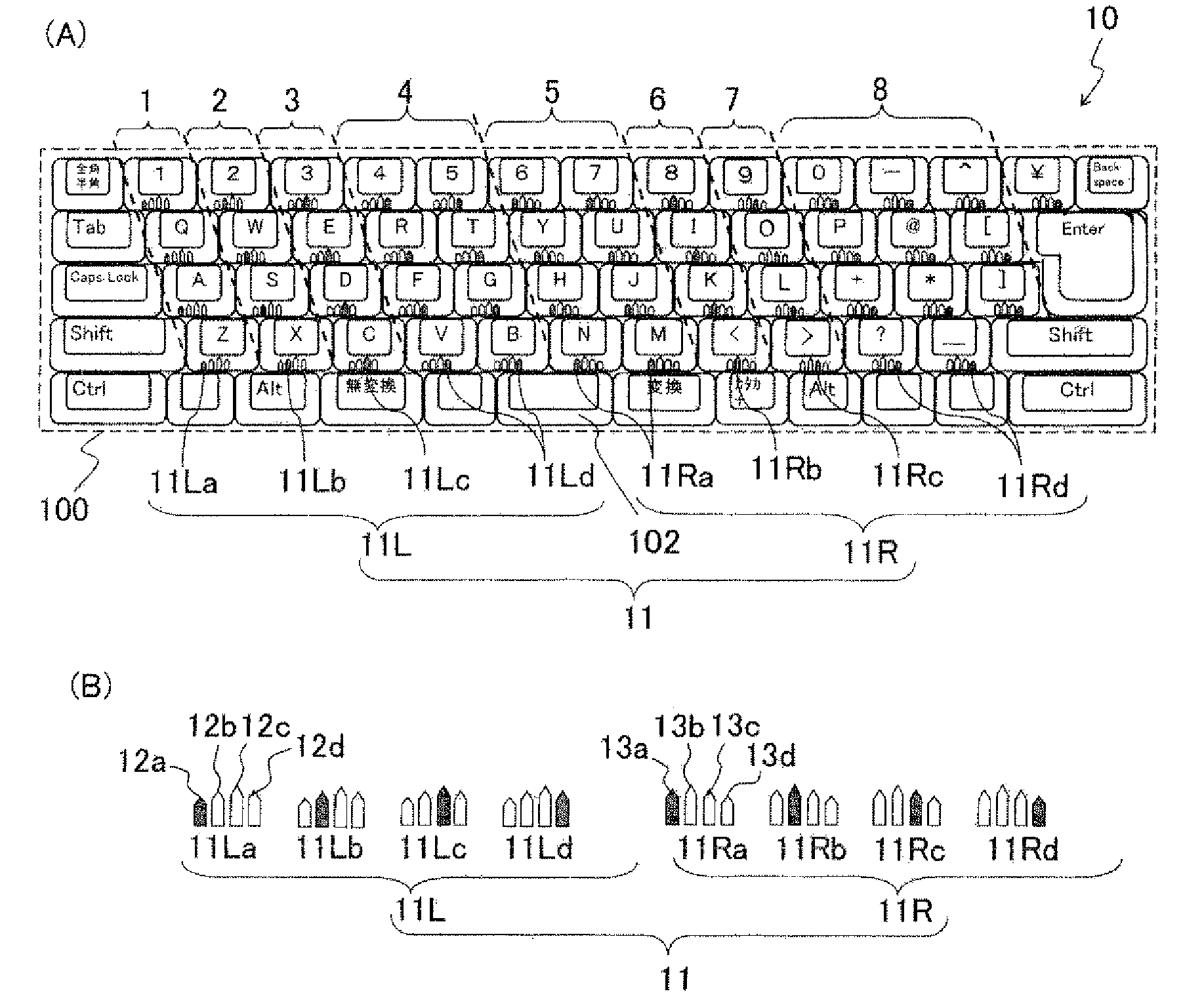
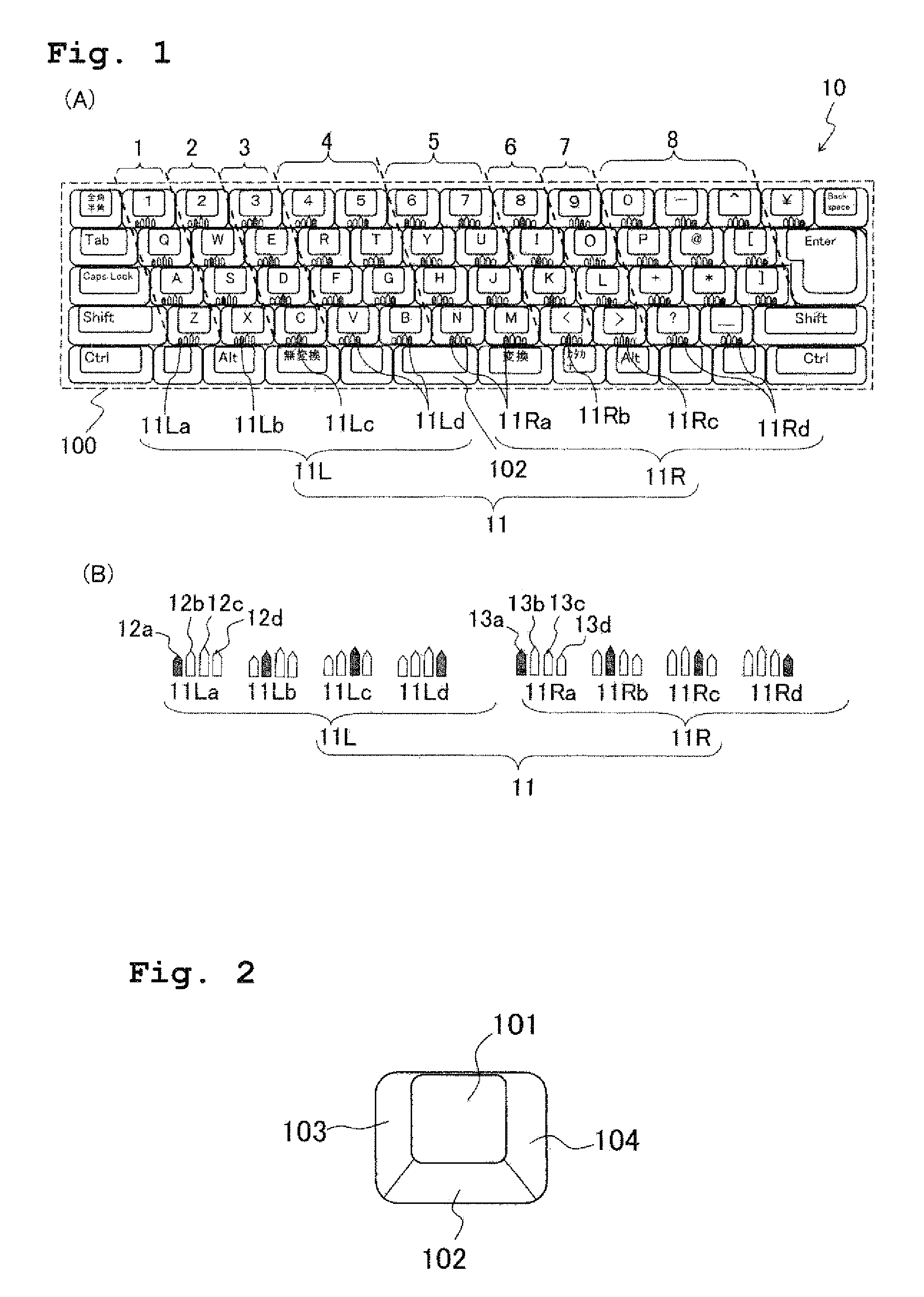
[0044]FIG. 1(A) shows a keyboard device according to the first embodiment. A keyboard device 10 has a board 100, character keys arranged in the “QWERTY” arrangement and supported on the board 100, an enter key supported on the board 100, and functions keys such as a shift key and a control key supported on the board 100. The character keys are formed to have identical shapes of a quadratic prism in which the bottom surface is larger to some extent than a key top (top surface) 101, and a front surface 102, a left surface 103 and a right surface 104 of the key are all trapezoid (FIG. 2). Note that all the corners of the key are chamfered, and the key top 101 is U-shaped in which the central portion of the key top 101 is sunken in the lateral direction. Each of the keys is supported on the board 100 by means of a method same as any known, conventional method for supporting keys on a keyboard device, and the keys may be supported by a leaf spring, a coil spring, etc. Further, the struct...

first modification

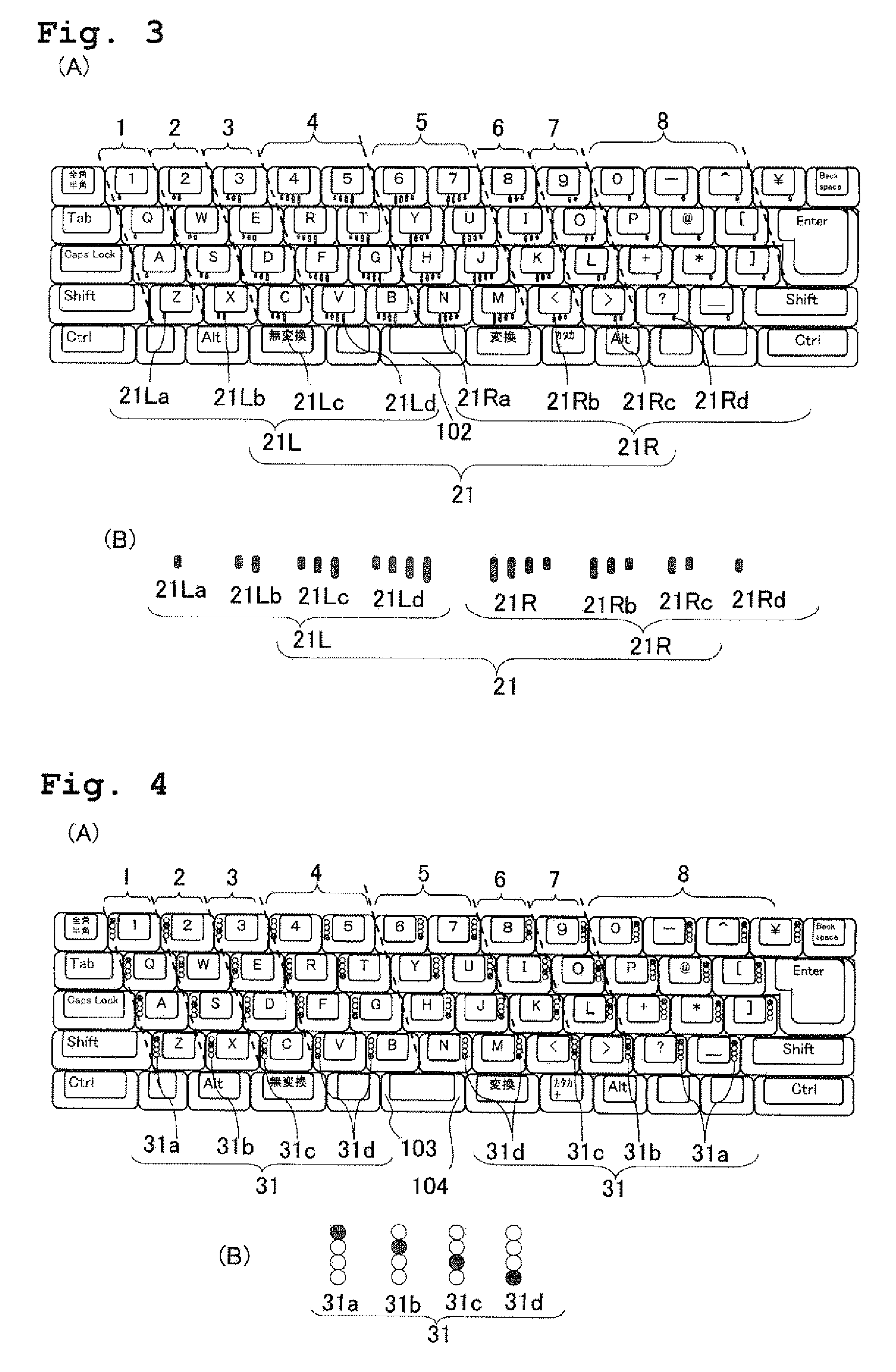
[0053]In the first modification, each of the character keys is provided with an identifier 21 formed as one, two, three or four projections raised from a side surface 102 on the front side of the character key. As shown in FIGS. 3(A) and 3(B), the projections are formed in a shape of vertically oblong ellipsoid, and are arranged in a horizontal row at regular intervals with upper ends of the projections being aligned. The shape and arrangement of the projections of the identifier 21 has a function of left-right identification as follows. With respect to the left hand region, a projection of an identifier 21L is provided on the front surface of the key from the left edge thereof. When there is a plurality of projections in the identifier 21L, then the projections are formed to be longer toward the right side. With respect to the right hand region, a projection of an identifier 21R is provided on the front surface of the key from the right edge thereof. When there is a plurality of pr...

second embodiment

[0054]FIG. 4(A) shows a keyboard device of the second embodiment. Each of the character keys is provided with an identifier 31 formed as four projection / recess portions projecting (raised) and recessed (sunk) from the left or right side wall surface of the character key. Each of the character keys in the left hand region has the identifier 31 on a left side surface 103 of the character key; and each of the character keys in the right hand region has the identifier 31 on a right side surface 104 of the character key. The identifier 31 is formed of four projection / recess portions aligned in the vertical direction, among which only one is a projection and remaining three are recesses. The projection / recess portions of identifiers 31a, 31b, 31c and 31d in the index, middle, ring and little finger areas respectively are formed such that the projection is provided only at the first, second, third and fourth position from the top, respectively (see FIG. 4(B)). Therefore, the left-right ide...


PUM


Abstract

A label having an identifier 41L is applied to the upper left corner of the key top of each character key in a left hand region of a keyboard device. A label having an identifier 41R is applied to the upper right corner of the key top of each character key in a right hand region. The identifier 41L is a mark of a reversed L shape and the identifier 41R is a mark of a mirror image pattern of the identifier 41L. Further, different colors are applied to the identifiers 41L and 41R depending on regions for individual fingers. As a consequence, the identifiers 41L and 41R have a function to visually display information representing which hand is to be used to press a key and information representing which finger is to be used to press the key. The keyboard device enables a user to naturally understand the arrangement of the keys and the use of the fingers.

Description

TECHNICAL FIELD[0001]The present invention relates to a keyboard device and a keyboard cover.BACKGROUND ART[0002]With the broad commercialization of personal computers, a wide range of consumers covering children to middle-aged and senior adults have begun to actively use the Internet, the multimedia, etc. via the personal computers. The reason the personal computers became so familiar to the wide range of consumers is because the operating system (OS) based on GUI (Graphical User Interface) is currently adopted in almost all the personal computers. Namely, owing to the GUI, the user can easily operate the personal computer by using a pointing device such as a mouse while looking at the display. Therefore, occasions, in which the user is required to perform input via the keyboard (hereinafter referred to as “key input”), have decreased substantially than with a conventional OS based on characters, which in turn makes the personal computer more user-friendly even to a user who is not...

Claims


Application Information

Patent Timeline
IPC IPC(8): G06F3/02
CPCG06F3/0202G06F3/0224G09F3/00G09B13/02G06F3/0489
Inventor KONDO, TOSHIHIKO
Owner KONDO TOSHIHIKO
Learn More