
Connector capable of preventing abrasion

Inactive Publication Date: 2006-01-12
FUJITSU LTD
View PDF32 Cites 8 Cited by
  • Summary
  • Abstract
  • Description
  • Claims
  • Application Information

AI Technical Summary

Benefits of technology

[0007] It is accordingly an object of the present invention to provide a connector contributing to a facilitated production and assembling. It is an object of the present invention to provide a connector capable of reducing the urging force of an elastic terminal or contact without inducing troublesome operations.
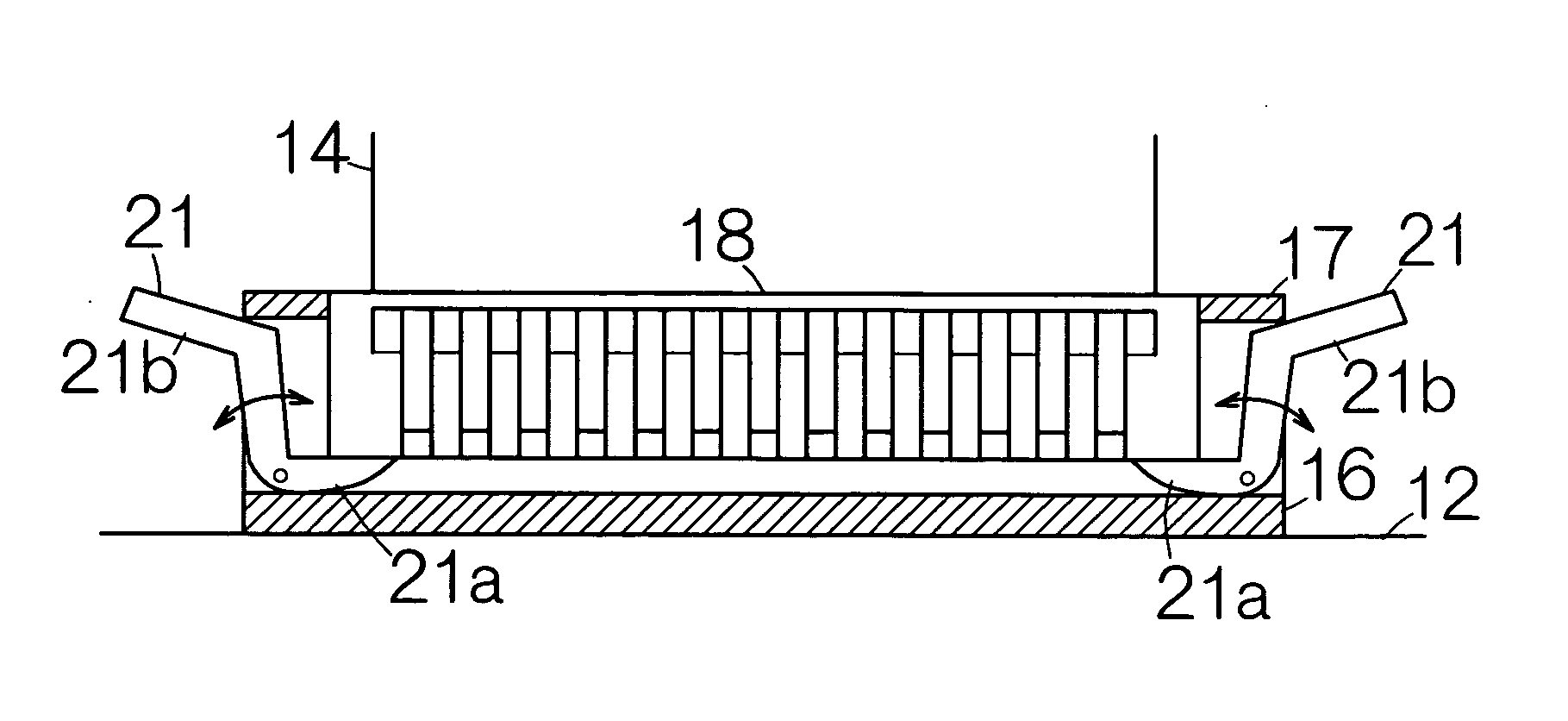
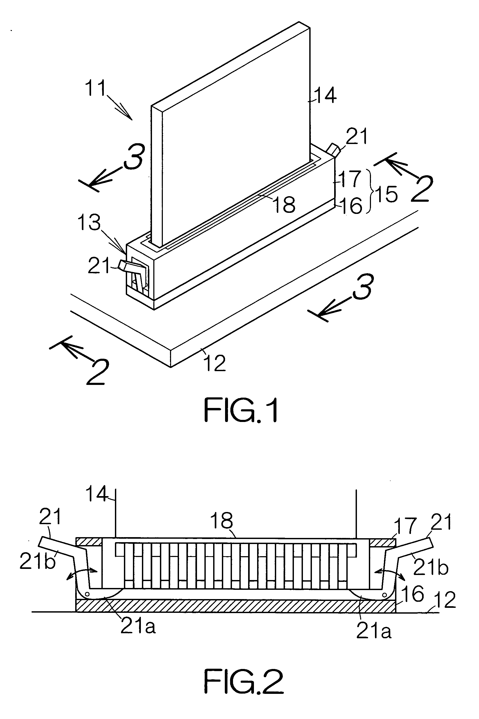
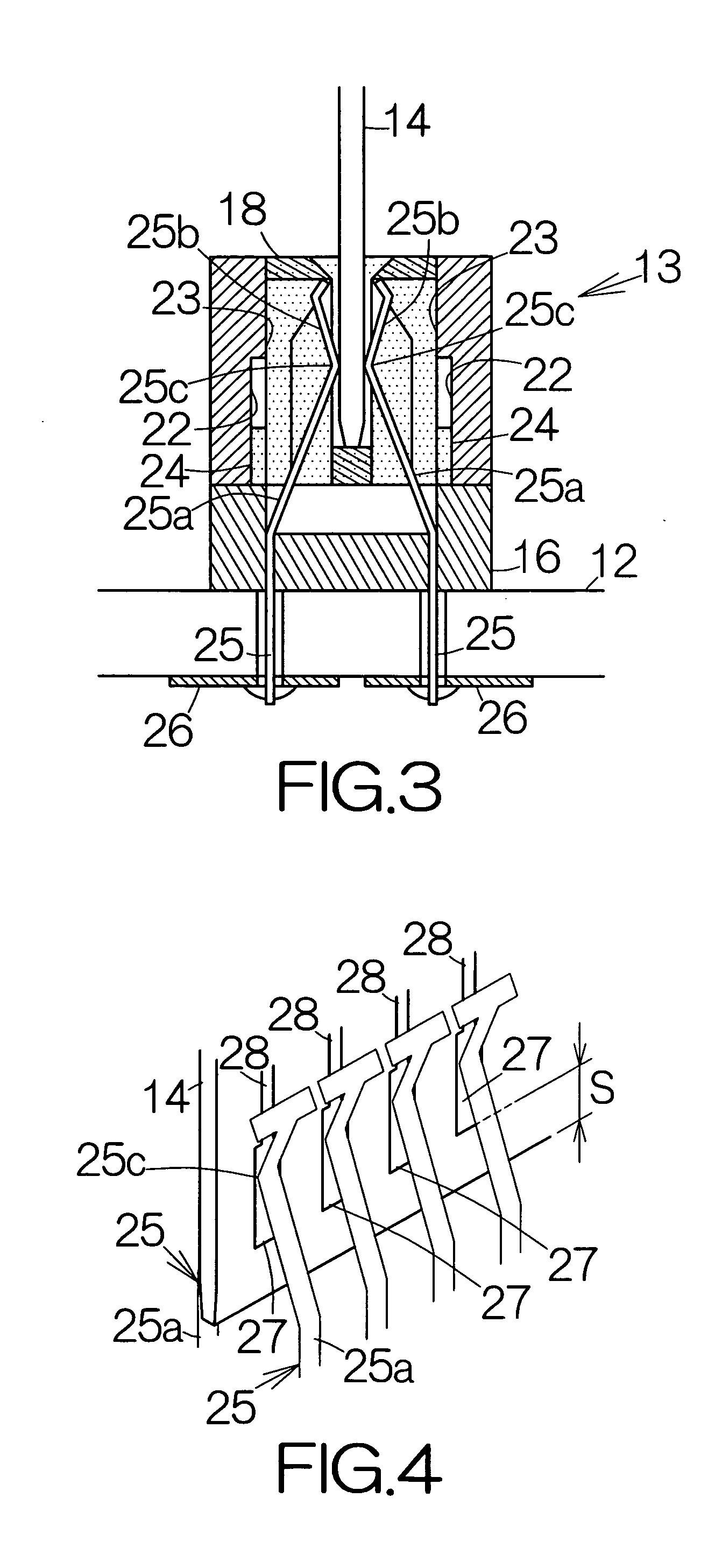
[0009] The movement of the slider enables displacement of the contact position between the inclined surface and the elastic terminal in the connector. The inclined surface generates a driving force directed to the elastic terminal in response to the movement of the slider. The elastic terminal is thus caused to deform. This deformation can be utilized to control the contact between the elastic terminal and a connective member inserted into the housing. The elastic terminal is simply allowed to contact the inclined surface of the slider in the production process of the connector, so that the slider can be assembled into the connector in a facilitated manner.
[0010] A receiving surface may be defined on the slider so as to receive a connective member inserted into the housing in parallel with the predetermined plane. The movement of the slider is caused in response to the insertion of the connective member in this structure. The simple insertion of the connective member induces the deformation of the elastic terminal. The contact can reliably be controlled between the connective member and the elastic terminal with conventional operations. The urging force of the elastic terminal can be adjusted without accompanying deteriorated operations.

Problems solved by technology

Frequent insertion and withdrawal of the card edge printed circuit board induces abrasion of the resin material in the card edge printed circuit board.
However, this structure suffers from troublesome operations to couple the sliding member to the contact in the production process of the connector.
The productivity thus gets deteriorated.
Insertion and withdrawal of the card edge printed circuit board also suffer from troublesome operations.

Method used


Image

  • Connector capable of preventing abrasion
  • Connector capable of preventing abrasion
  • Connector capable of preventing abrasion

Examples


Embodiment Construction

[0026]FIG. 1 schematically illustrates a printed circuit board unit 11. The printed circuit board unit 11 includes a printed circuit board 12. A connector 13 is mounted on the printed circuit board 12. The connector 13 stands upright from the surface of the printed circuit board 12. A small-sized printed circuit board or so-called card edge printed circuit board 14 is inserted into the connector 13. The card edge printed circuit board 14 is kept in an attitude upright to the printed circuit board 12. The card edge printed circuit board 14 corresponds to a graphic board, a memory board, a PCI board, or other types of printed circuit board, for example. The connector 13 serves to establish electric connection between the card edge printed circuit board 14 and the printed circuit board 12 as described later in detail.

[0027] The connector 13 includes a housing 15. The housing 15 has a plate-shaped base 16 received on the surface of the printed circuit board 12. A housing body 17 is cou...


PUM


Abstract

A slider is incorporated in a connector. A guide is designed to guide movement of the slider along a predetermined plane. An elastic terminal or contact extends to the free tip end from the stationary end. An inclined surface is defined on the slider so as to receive the elastic terminal. The inclined surface extends along an imaginary plane intersecting an imaginary reference plane including the predetermined plane by a predetermined inclination angle. The movement of the slider enables displacement of the contact position between the inclined surface and the elastic terminal in the connector. The inclined surface generates a driving force directed to the elastic terminal in response to the movement of the slider. The elastic terminal is thus caused to deform. This deformation can be utilized to control the contact between the elastic terminal and a connective member to be connected.

Description

BACKGROUND OF THE INVENTION [0001] 1. Field of the Invention [0002] The present invention relates to a connector designed establish connection between at least a pair of electrical conductor. In particular, the present invention relates to a connector designed to receive a printed circuit board such as a co-called card edge printed circuit board. [0003] 2. Description of the Prior Art [0004] Some connectors are well known to receive a so-called card edge printed circuit board. Pairs of elastic terminals or contacts are fixed within a housing of the connector, for example. The individual contacts extend from the stationary end, fixed to the housing, to the free tip end. When the card edge printed circuit board is inserted into the housing of the connector, the card edge printed circuit board is held between the contacts of the individual pairs. The card edge printed circuit board is thus stationarily coupled to the connector. [0005] The individual contacts are strongly urged against ...

Claims


Application Information

Patent Timeline
IPC IPC(8): H01R13/15
CPCH01R13/055H01R12/721H01R12/7005H01R13/631
Inventor ISHIKAWA, KOJI
Owner FUJITSU LTD
Learn More