
Portable Pouch Heating Unit

a heating unit and pouch technology, applied in the direction of lighting and heating equipment, heating types, sustainable buildings, etc., can solve the problems of asphalt patch above the given temperature, affecting driving surfaces, and affecting the uniform distribution of hea

Inactive Publication Date: 2009-05-07
GREENHEAT IP HLDG LLC
View PDF99 Cites 43 Cited by
  • Summary
  • Abstract
  • Description
  • Claims
  • Application Information

AI Technical Summary

Benefits of technology

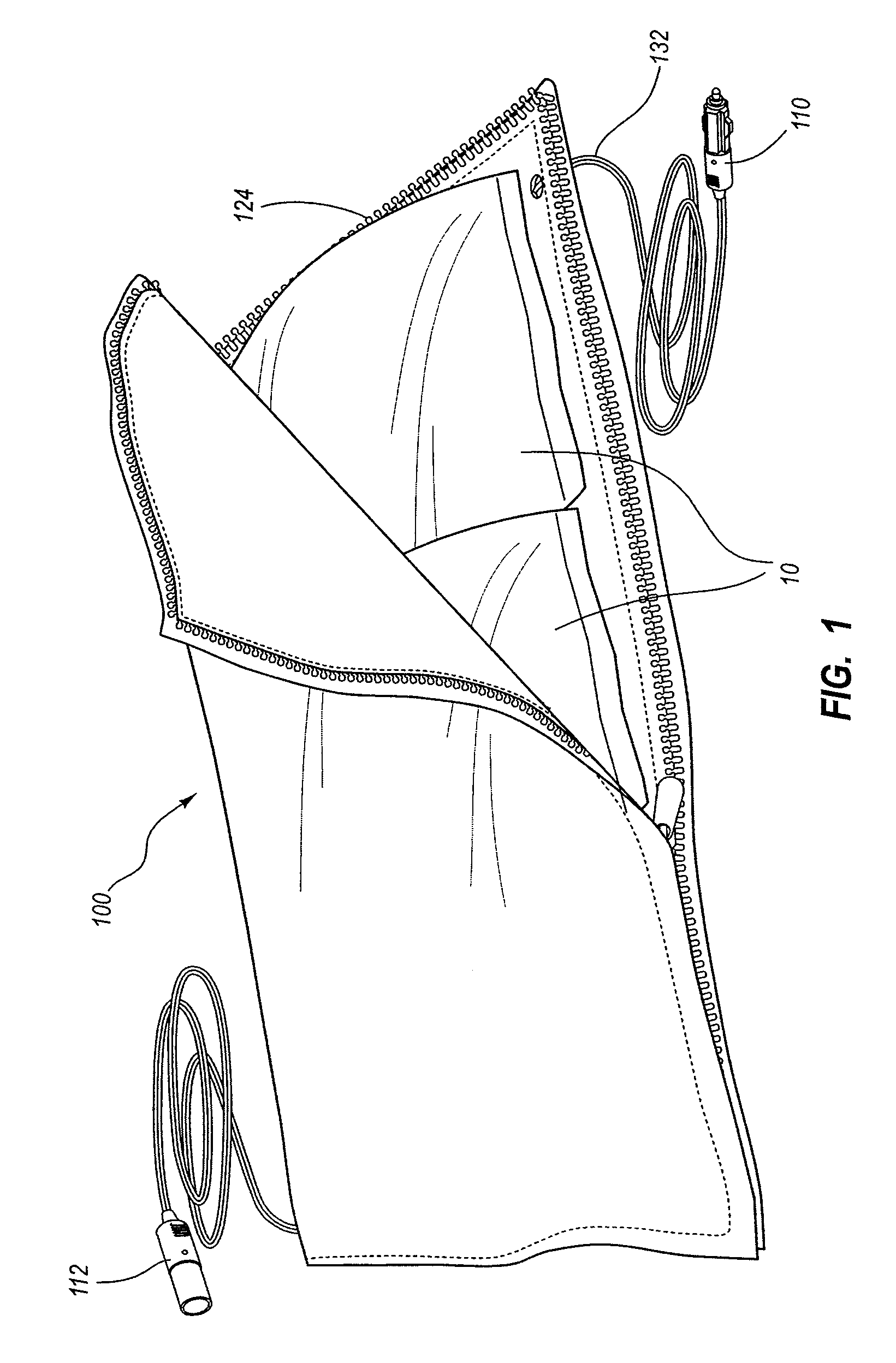
[0005]One embodiment described herein is directed to a portable pouch for use in providing evenly distributed heat to temperature sensitive materials. The portable pouch includes a heating unit that has one or more fasteners attached around its outer edges. The heating unit can be folded to enable the one or more fasteners to secure together opposing outer edges of the heating unit, thereby forming a substantially enclosed pocket for receiving materials to be warmed. In one embodiment, the pocket formed by the heating unit is sized to receive one or more bags of asphalt patch. The heating unit can be adapted for electrical connection to a direct current power source, such as an automotive power source.

Problems solved by technology

Changing weather can affect driving surfaces.
For example, the expansion and contraction of asphalt paved surfaces during winter months caused by the cycling of the temperature of the asphalt paved surfaces due to alternating exposure to sun and snow can cause potholes in the asphalt driving surfaces.
However, cold weather conditions can make maintaining the asphalt patch above the given temperature a challenge.
Cities and other municipalities often discard as much as 40% of asphalt patch purchased, because it cannot be maintained at an appropriate temperature

Method used


Image

  • Portable Pouch Heating Unit
  • Portable Pouch Heating Unit
  • Portable Pouch Heating Unit

Examples


Embodiment Construction

[0016]Disclosed herein are embodiments of a heating unit for use in asphalt patch or other warming applications. In particular, embodiments may include a heating unit configured to substantially cover or enclose the entire outer surface of one or more bags, packages, or containers of asphalt patch. While the heating unit of the present invention is described as being used to heat bags, packages, or containers of asphalt patch, it will be appreciated that the heating unit may also be used to provide heat to other objects and materials.

[0017]Embodiments of the heating unit disclosed herein can be used in direct current applications, such as automotive or other applications using direct current power supplies. Illustrated embodiments include details related to direct current (DC) embodiments, and in particular, some embodiments are particularly suited for 12V DC automotive embodiments. This allows for the heating unit to be used in a number of unique and novel ways. For example, while ...


PUM


Abstract

A portable pouch for use in heating temperature sensitive materials is disclosed. The pouch includes a heating unit with one or more fasteners attached around its outer edges. The heating unit can be folded to allow the one or more fasteners to secure opposing outer edges of the heating unit together to form a pocket for substantially enclosing the materials to be warmed. The heating unit can be electrically connected to a direct current power source. The heating unit includes first and second cover layers enclosing a heat generating element and a carbon-based heat spreading element. A thermal insulation layer is also positioned between the first and the second cover layers. The heating element is adapted to generate and evenly spread heat over the interior surface of the pocket to evenly heat the materials disposed within the pocket.

Description

CROSS-REFERENCE TO RELATED APPLICATIONS[0001]This application is a continuation in part of co-pending U.S. application Ser. No. 11 / 835,641 filed on Aug. 8, 2007 titled GROUNDED MODULAR HEATED COVER, which is a continuation in part of U.S. patent application Ser. No. 11 / 744,163 filed May 3, 2007, which is a continuation in part of U.S. patent application Ser. No. 11 / 218,156 filed Sep. 1, 2005, now U.S. Pat. No. 7,230,213, issued on June 12, 2007. This application is also a continuation in part of co-pending U.S. application Ser. No. 11 / 422,580 filed on Jun. 6, 2006, titled “A RADIANT HEATING APPARATUS” which claims priority to U.S. Provisional Patent Application 60 / 688,146 filed Jun. 6, 2005, titled LAMINATE HEATING APPARATUS. U.S. application Ser. No. 11 / 422,580 filed on Jun. 6, 2006, titled “A RADIANT HEATING APPARATUS” is a Continuation in Part of U.S. patent application Ser. No. 11 / 218,156, filed Sep. 1, 2005, now U.S. Pat. No. 7,230,213 issued on Jun. 12, 2007, which claims prio...

Claims


Application Information

Patent Timeline
Patent Type & Authority Applications(United States)
IPC IPC(8): H05B3/02H05B3/34H05B1/02
CPCF24D13/022H05B1/0236H05B1/0275Y02B30/26H05B2203/003H05B2203/014H05B2203/017H05B3/36Y02B30/00
Inventor NAYLOR, DAVIDDAY, KEVINCATERINA, THOMAS
Owner GREENHEAT IP HLDG LLC
Learn More