
Explosive charge

a technology of explosive charge and charge, applied in the field of explosive charge, can solve the problems of significant growth of the total mass in a technical device, increased explosive quantity is not a suitable measure, and destructive action at a greater distance, and achieves the effect of contributing to the overall

Active Publication Date: 2009-05-07
FRAUNHOFER GESELLSCHAFT ZUR FOERDERUNG DER ANGEWANDTEN FORSCHUNG EV
View PDF35 Cites 0 Cited by
  • Summary
  • Abstract
  • Description
  • Claims
  • Application Information

AI Technical Summary

Benefits of technology

[0017]The invention is based on refining an explosive charge which has a spatial shape comprising explosive material and, in the course of the explosion, unfolds a spatially anisotropic pressure action in at least one main action direction, in which the pressure action is greater than in other action directions, as is the case in the cylindrical charge explained above, for example, in such a way that a significant improvement of the range of the pressure action and also of the spatial focusing ability of the pressure action upon the detonation is to be achieved. Thus, in particular a control of the oriented propagation of the pressure action in a sharply defined spatial direction is to be possible. Bodies or splinters propagating like a jet or projectile are expressly to be avoided, particularly because their range cannot be limited or can only be limited with great difficulty.
[0026]Thus, ignition points situated distributed around the axis of symmetry of the plate-shaped spatial shape may be ignited with a predefined specific time sequence and also with a specific predefined ignition triggering pattern, which does not necessarily provide the triggering of all existing ignition points, but rather only a selective selection of existing ignition points. In this way it is possible to vary the spatial main action direction along which focusing of the detonation-related pressure waves occur in a predefinable way without changing the orientation of the spatial shape of the explosive charge.
[0033]The application of the particles or a material layer disintegrating into particles due to detonation on the concavely implemented surface area of the spatial shape is preferably performed using adhesively acting substances for producing an intimate connection between particles and spatial shape, which are in turn selected suitably and may thus provide a positive contribution to the overall effect.
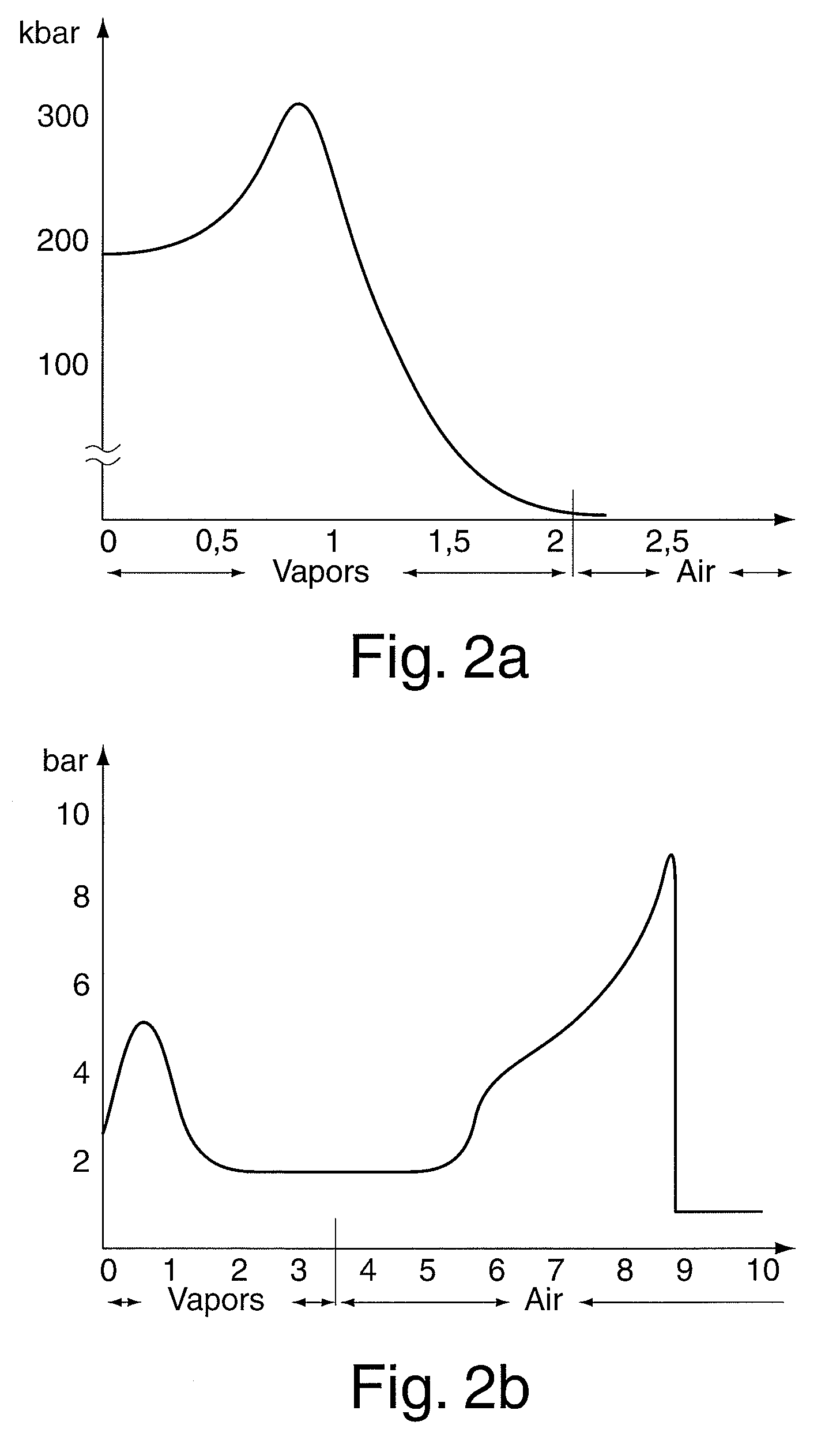
[0034]In addition, the particle cloud may be prevented from propagating in an uncontrolled way far from the location of the detonation by the selection of the particle size and thus also the mass of the particles, as is the case, for example, with the penetrators made of conventional projectile explosive charges. The explosive charge according to the solution allows spatially extremely directed pressure action, whose action width is predefinable. The pressure action at a large distance from the location of the explosive charge may be comparable to the action of a spherical charge which is directly in contact with a target structure. It is essential that the extremely high pressure action of the explosive charge implemented according to the invention at a large distance from the charge only unfolds in a defined spatial angle range whose direction may essentially be predefined by the geometrical implementation of the spatial shape and the mode of ignition. The range of the particle cloud may be influenced by the selection of size, mass, and shape of the individual particles for a given particle total mass and explosive quantity.

Problems solved by technology

If a range increase of the pressure action is desired, increasing the explosive quantity is not a suitable measure.
The energy released in the near field, that is, in the immediate surroundings of the explosive, is partially exploited to accelerate these fragments, for example, in the form of splinters, which subsequently propagate over relatively large distances, limited by the deceleration due to aerodynamic forces, and may thus cause a destructive action at a greater distance.
However, this is connected with a significant growth of the total mass in a technical device, which is not acceptable for specific applications, in particular in cases in which the mass of the dam must be significantly greater than the explosive mass.

Method used


Image

  • Explosive charge
  • Explosive charge
  • Explosive charge

Examples


Embodiment Construction

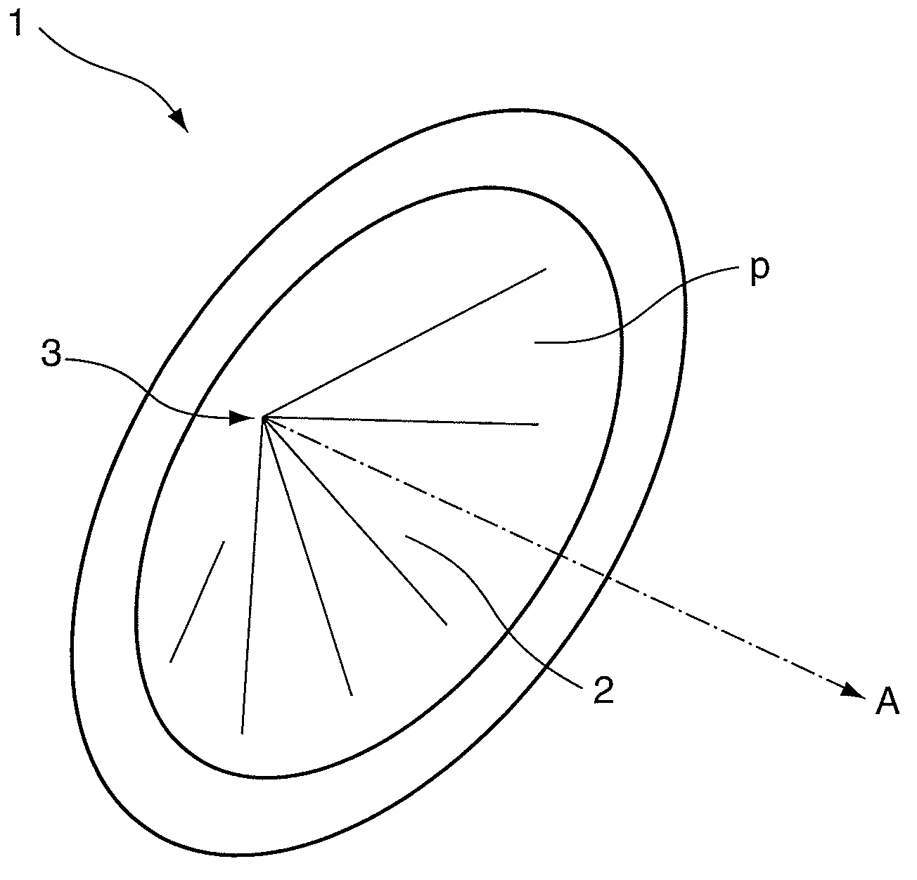
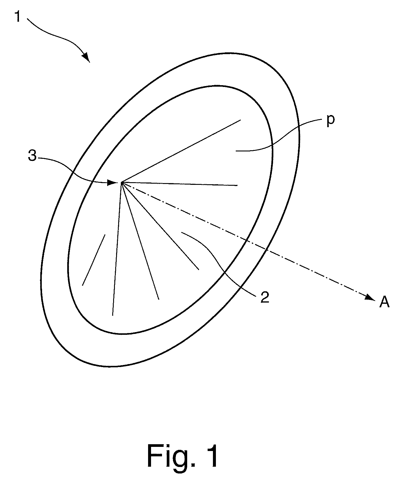
[0040]In the explosive charge according to the invention, which finally results solely and alone through the combination of a specific predefined spatial shape made of explosive material and particles provided on a specific surface area of the spatial shape and / or a material layer which disintegrates into particles by the detonation, it is essentially important that the geometrical implementation of the spatial shape and the choice of the explosive material are selected in such a way that a chronological spatial course of the front of the propagating chemical material conversion and an accompanying resulting vapor formation through the free atmosphere which are favorable for the further propagation result as a function of the mode of ignition.

[0041]For example, the flat-cone charge shown in perspective in FIG. 1 fulfills the case of a rotationally-symmetric spatial shape oriented on a spatial point. The explosive charge 1 implemented as a flat cone has a concave surface area 2, whic...


PUM


Abstract

An explosive charge is disclosed which has a spatial shape comprising explosive material and, in the course of the explosion, unfolds a spatially anisotropic pressure action in at least one main action direction, in which the pressure action is greater than in the other action directions. The spatial shape comprising the explosive material has a surface area facing toward the at least one main action direction and extends in the at least one main action direction, particles are applied and / or a material layer disintegrating into particles during the explosion is applied to the surface area, the particles comprise a nonexplosive material, and a total mass of the particles is less than a mass of the explosive material.

Description

BACKGROUND OF THE INVENTION[0001]1. Field of the Invention[0002]The invention relates to an explosive charge which has a spatial shape comprising explosive material and which, in the course of the explosion, unfolds a spatially anisotropic pressure action in at least one main action direction, in which the pressure action is greater than in other directions.[0003]2. Description of the Prior Art[0004]A detonation of explosive generates, as a function of the quantity, configuration, and composition of the explosive, a strong pressure action in the environment of the location at which the detonation occurs. The pressure action is typically based on a chemical reaction of the explosive to form gaseous reaction products, the so-called vapors, which propagate at high velocities and at high temperature and density because of the large pressure differential to the environment. A propagating pressure wave is also generated in the surrounding air by the expanding vapors, which typically rushe...

Claims


Application Information

Patent Timeline
Patent Type & Authority Applications(United States)
IPC IPC(8): F42B1/024
CPCF42B1/02F42B1/028
Inventor HEINE, ANDREASWICKERT, MATTHIASTHOMA, KLAUS
Owner FRAUNHOFER GESELLSCHAFT ZUR FOERDERUNG DER ANGEWANDTEN FORSCHUNG EV
Learn More