
Engine intake control apparatus

a technology of engine intake and control apparatus, which is applied in the direction of electric control, combustion engines, machines/engines, etc., can solve the problems of deteriorating opening and closing accuracy of the opening and closing of the throttle valve by the motor, difficult to maintain properly the inter-shaft distance between a pinion gear and a pinion gear, etc., to accurately define accurate opening and closing of the throttle valve, and accurate definition of the mutual positional relationship

Active Publication Date: 2017-02-07
HITACHI ASTEMO LTD
View PDF4 Cites 0 Cited by
  • Summary
  • Abstract
  • Description
  • Claims
  • Application Information

AI Technical Summary

Benefits of technology

[0005]In view of the above-mentioned problems, it is preferable to provide an engine intake control apparatus which is capable of implementing with high accuracy the mutual positioning between the three components, i.e. a motor support plate, a cover and a throttle valve body, and capable of effectively improving the opening and closing accuracy for the opening and closing of a throttle valve by a motor.
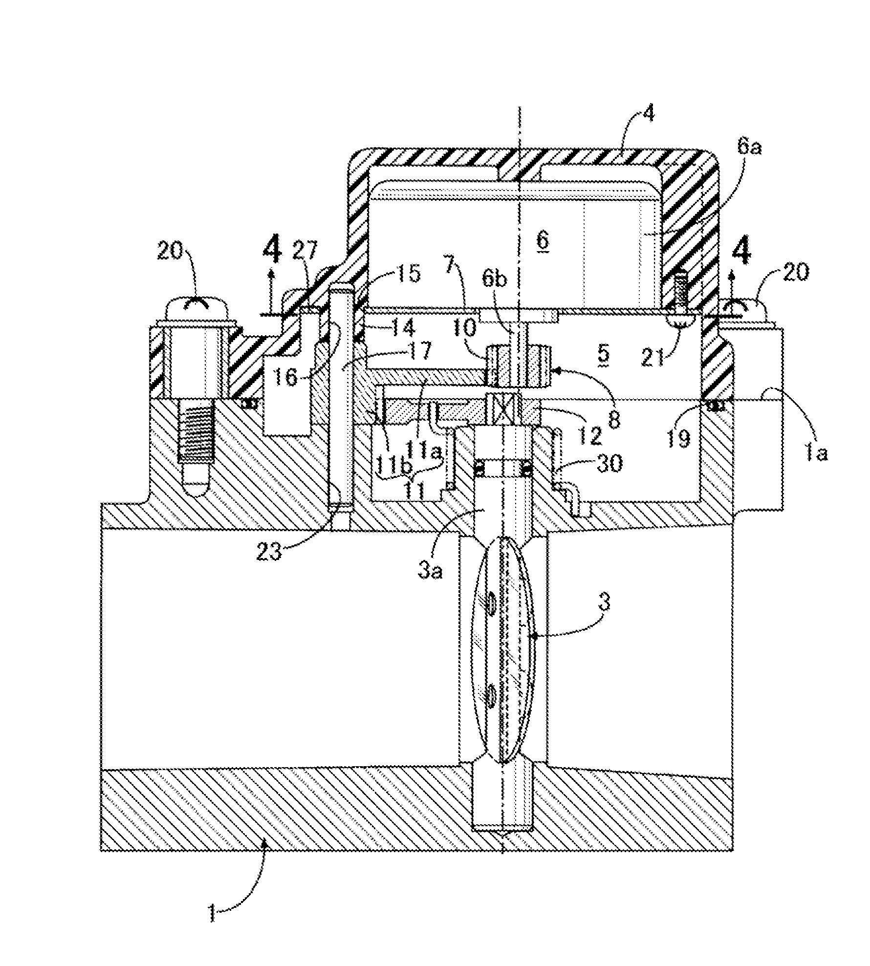
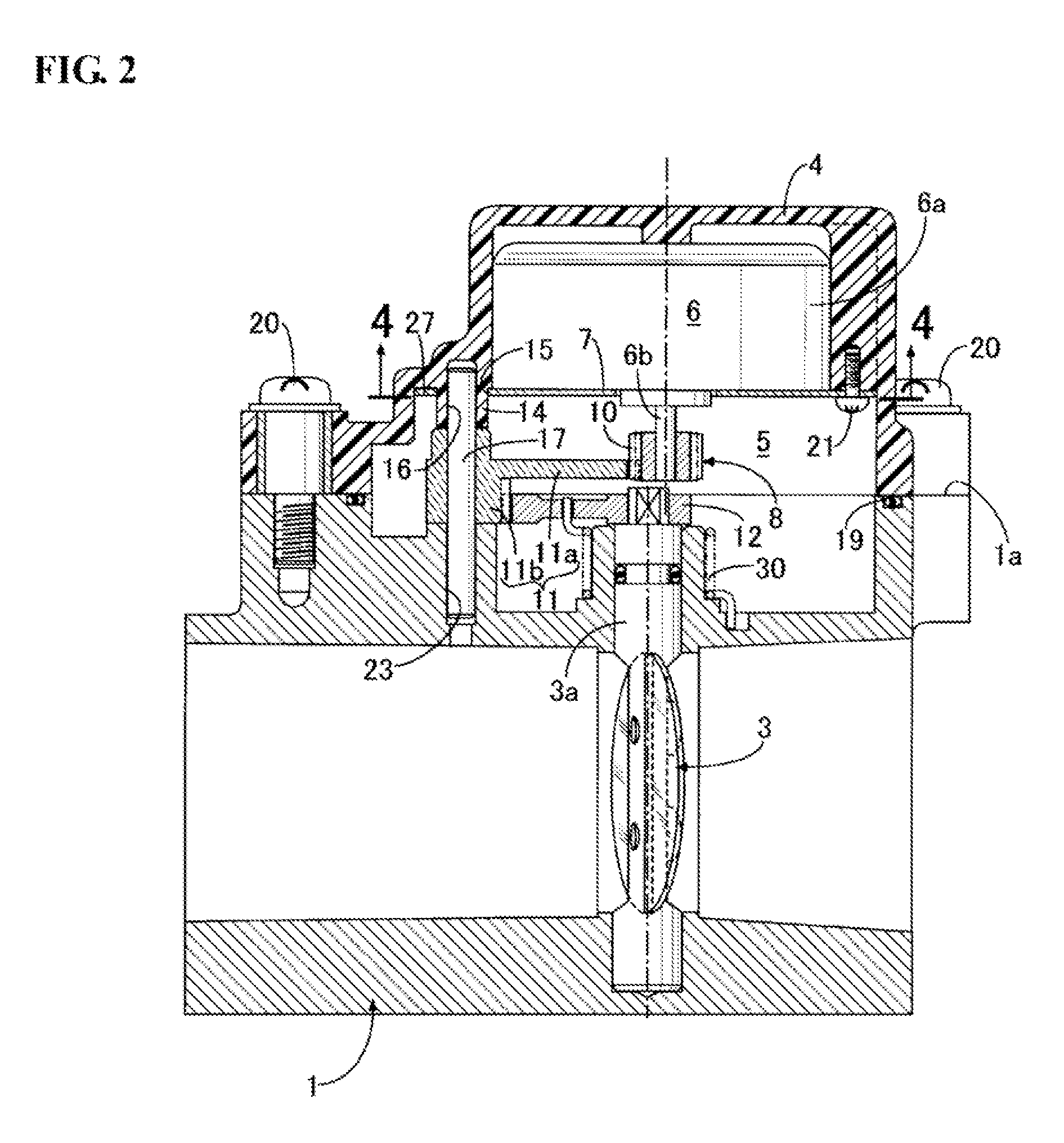
[0009]According to the first feature, the cover is made of synthetic resin, the motor support plate is made of metal, there is integrally formed a positioning boss on the cover, a first positioning hole arranged on the motor support plate is fitted on an outer peripheral surface of the positioning boss, and the positioning boss is positioned and fitted with the throttle valve body each other. Consequently, it is possible to accurately define the mutual positional relationship between the three components, i.e. the cover, the motor support plate and the throttle valve body. As a result, it is possible to obtain the inter-shaft distance of the pinion gear and the output gear as specified, and it is possible to always maintain a proper back lash of the respective parts of the reduction gear row, thereby enabling accurate opening and closing of the throttle valve by the motor. Moreover, since the motor is covered by the cover made of synthetic resin, and the motor support plate made of metal is supported by the positioning boss integrated with the cover, even if an electric leakage is produced from the electric generator on the engine side to the side of the throttle valve body, it is possible to prevent the motor from being short-circuited by the cover, thereby protecting the motor.
[0010]According to the second feature, a second positioning hole parallel to the rotor shaft is formed on the positioning boss, a positioning shaft arranged to extend in parallel with the valve shaft from the side of the throttle valve body, is fitted with the second positioning hole, the reduction gear row is constituted by a pinion gear provided on the rotor shaft, an intermediate gear block and an output gear, the intermediate gear block is constituted by a large-diameter intermediate gear engaging with the pinion gear, and a small-diameter intermediate gear which is integrally formed on one side face of the large-diameter intermediate gear, the output gear is provided on the valve shaft and engages with the small-diameter intermediate gear, and the intermediate gear block is supported by the positioning shaft. Consequently, it is possible to accurately define the mutual positional relationship between the three components, i.e. the pinion gear, the intermediate gear block and the output gear, enabling more appropriate adjustment of the back lash between the respective gears. Moreover, the positioning shaft also serves as a fulcrum shaft of the intermediate gear block, enabling positive contribution to reduction of the number of components and simplification of the structure. Further, since the positioning boss is supported by the positioning shaft and the throttle valve body which is made of metal and has high rigidity, and the positioning boss is fitted in the first positioning hole of the motor support plate, even if there is thermal expansion or contraction in the cover made of synthetic resin, the positions of the positioning shaft and the positioning boss will not change. Therefore, it is possible to always maintain an appropriate back lash between the respective gears.
[0011]According to the third feature, since the pinion gear and the output gear is configured such that the side faces of the pinion gear and the output gear face each other, it is possible to realize the compaction of the reduction gear row, thereby realizing the compaction of the cover accommodating the reduction gear row.

Problems solved by technology

Since the mutual positioning between the motor support plate, the cover and the throttle valve body is not given special consideration, due to error accumulation in the assembling process, it is difficult to maintain properly the inter-shaft distance between a pinion gear provided on the rotor shaft of the motor, and an output gear provided on the valve shaft of the throttle valve.
Therefore, the back lash of the reduction gear row is uneven, which may cause the opening and closing accuracy for the opening and closing of the throttle valve by the motor to deteriorate.

Method used


Image

  • Engine intake control apparatus
  • Engine intake control apparatus
  • Engine intake control apparatus

Examples


Embodiment Construction

[0016]Embodiments of the present disclosure will be described below with reference to the accompanying drawings.

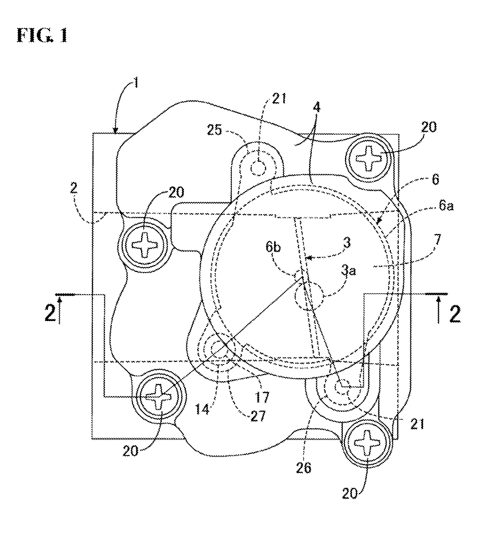
[0017]In FIG. 1 to FIG. 3, a throttle valve body 1 connected with an intake system on a general-purpose engine or a vehicle engine, has an intake passage 2 connected to an intake port of the above-mentioned engine. A valve shaft 3a of a throttle valve 3 for opening and closing the intake passage 2, is rotatably supported by the throttle valve body 1.

[0018]A cover 4 made of synthetic resin is jointed, by a plurality of bolts 20, on one side face 1a of the throttle valve body 1, which is perpendicular to the axis of the valve shaft 3a, and a speed reduction chamber 5 is defined between the throttle valve body 1 and the cover 4. An O-ring 19 surrounding the speed reduction chamber 5 is mounted between the jointing surfaces of the throttle valve body 1 and the cover 4. In the speed reduction chamber 5, there are accommodated: a stepping motor 6; a motor support plate 7 made of...


PUM


Abstract

In an engine intake control apparatus, a cover is made of synthetic resin, a motor support plate is made of metal, a positioning boss is integrally formed on the cover, a first positioning hole arranged on a motor support plate is fitted on an outer peripheral surface of the positioning boss, and the positioning boss is positioned and fitted with a throttle valve body each other. With such an engine intake control apparatus, it is possible to perform with high accuracy the mutual positioning between the three components, i.e. the motor support plate, the cover and the throttle valve body, and it is possible to effectively improve the opening and closing accuracy for the opening and closing of the throttle valve by the motor.

Description

CROSS REFERENCES TO RELATED APPLICATIONS[0001]The present application claims priority under 35 U.S.C. §119 to Japanese Patent Application No. 2013-50447, filed Mar. 13, 2013, entitled “Engine Intake Control Apparatus.” The contents of this application are incorporated herein by reference in their entirety.TECHNICAL FIELD[0002]The present disclosure relates to an improvement of an engine intake control apparatus. On one side face of a throttle valve body of the intake control apparatus, a cover in which a speed reduction chamber is defined, is jointed. The throttle valve body has an intake passage which is opened and closed by a throttle valve, and supports a valve shaft of the throttle valve for opening and closing the intake passage. In the speed reduction chamber, there are accommodated: a motor, a motor support plate for supporting a stator of the motor and attached to the cover, and a reduction gear row for decelerating and transferring the rotation of a rotor shaft of the motor...

Claims


Application Information

Patent Timeline
Patent Type & Authority Patents(United States)
IPC IPC(8): F02D41/00F02D9/10F02D11/10F02D9/08
CPCF02D41/0002F02D9/106F02D9/108F02D9/1035F02D9/1065F02D11/10Y02T10/42Y02T10/40
Inventor SHISHIDO, YOSHIKUNIHAGIYA, MASAKOKUMAGAI, YUONO, YASUSHI
Owner HITACHI ASTEMO LTD
Learn More