Set trigger for a firearm

a technology for setting the trigger and firearms, which is applied in the direction of firing/trigger mechanisms, weapons, weapon components, etc., can solve the problems of inability to accurately fire rifles, increased resistance on the trigger, and increased difficulty in disassembly and assembly, so as to reduce the pressure required to fire rifles and reduce the resistance on the trigger. , the effect of easy assembly and disassembly

Inactive Publication Date: 2009-05-07
DSA AN ILLINOIS CORP
View PDF20 Cites 6 Cited by
  • Summary
  • Abstract
  • Description
  • Claims
  • Application Information

AI Technical Summary

Benefits of technology

[0007]It is the object of the invention to provide an adjustable Set Trigger for a FAL or similar rifle of the character described.
[0008]Another object is to provide a Set Trigger that can be easily assembled and disassembled to allow for cleaning of the rifle.
[0009]Another object is to provide a Set Trigger that operates with the existing trigger assembly except for the addition of structure allowing the user either to use the trigger as a standard trigger or for a user to use the set trigger to reduce the pressure required to fire the rifle.
[0010]Another object is to provide a device which selectively is capable of reducing resistance on the trigger at the time of firing while allowing the user to operate the weapon with one hand on the grip.
[0011]Another object is to provide a device selectively to reduce resistance on the trigger at any time prior to firing without removing the grip and thereby avoiding exposure of the trigger assembly to the elements or loss of trigger assembly parts.
[0012]Another object is to provide a device to reduce resistance on the trigger at any time prior to firing without need to replace either the spring or the screw in the trigger assembly.

Problems solved by technology

The result of inadvertent movement is that the person would shoot less accurately.
This problem is particularly serious where accuracy is key such as in competition shooting and sniper shooting.
Conversely, if the trigger is adjusted such that resistance is at a minimum, then the rifle is likely to fire inadvertently.
A hair trigger is regarded as a safety hazard.
Some would try to grind or polish the engagement surface of the hammer and the sear nose but those techniques could adversely affect the operation of the firearm depending on the method and extent of the change to those components.
Any steps taken in the field would not be practical and may be dangerous.

Method used


Image

  • Set trigger for a firearm
  • Set trigger for a firearm
  • Set trigger for a firearm

Examples


Embodiment Construction

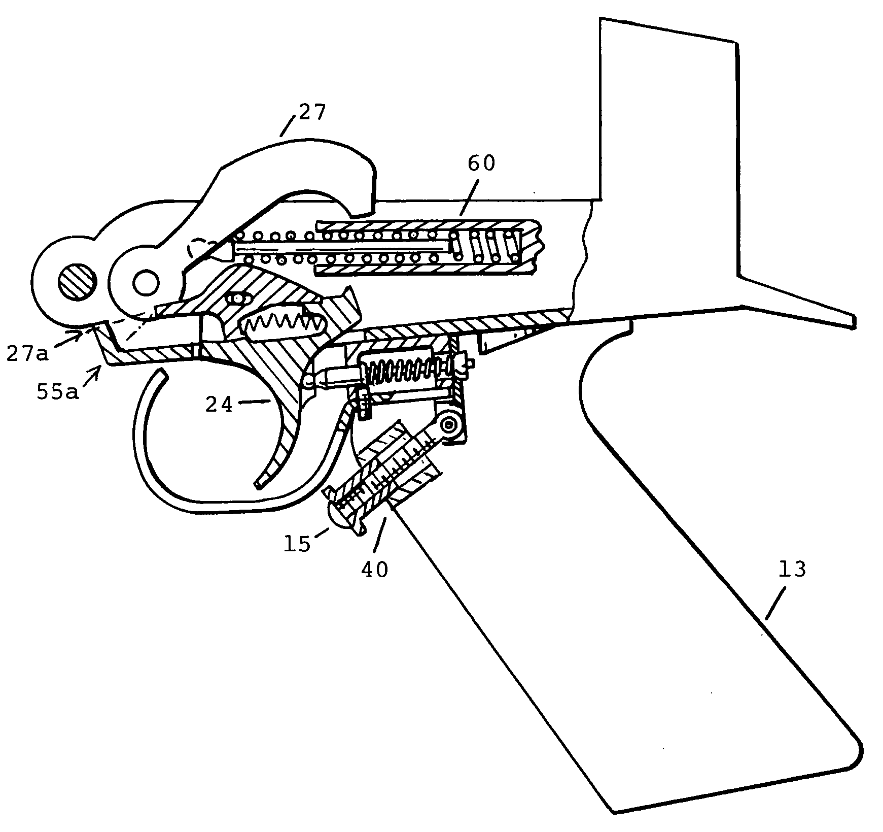
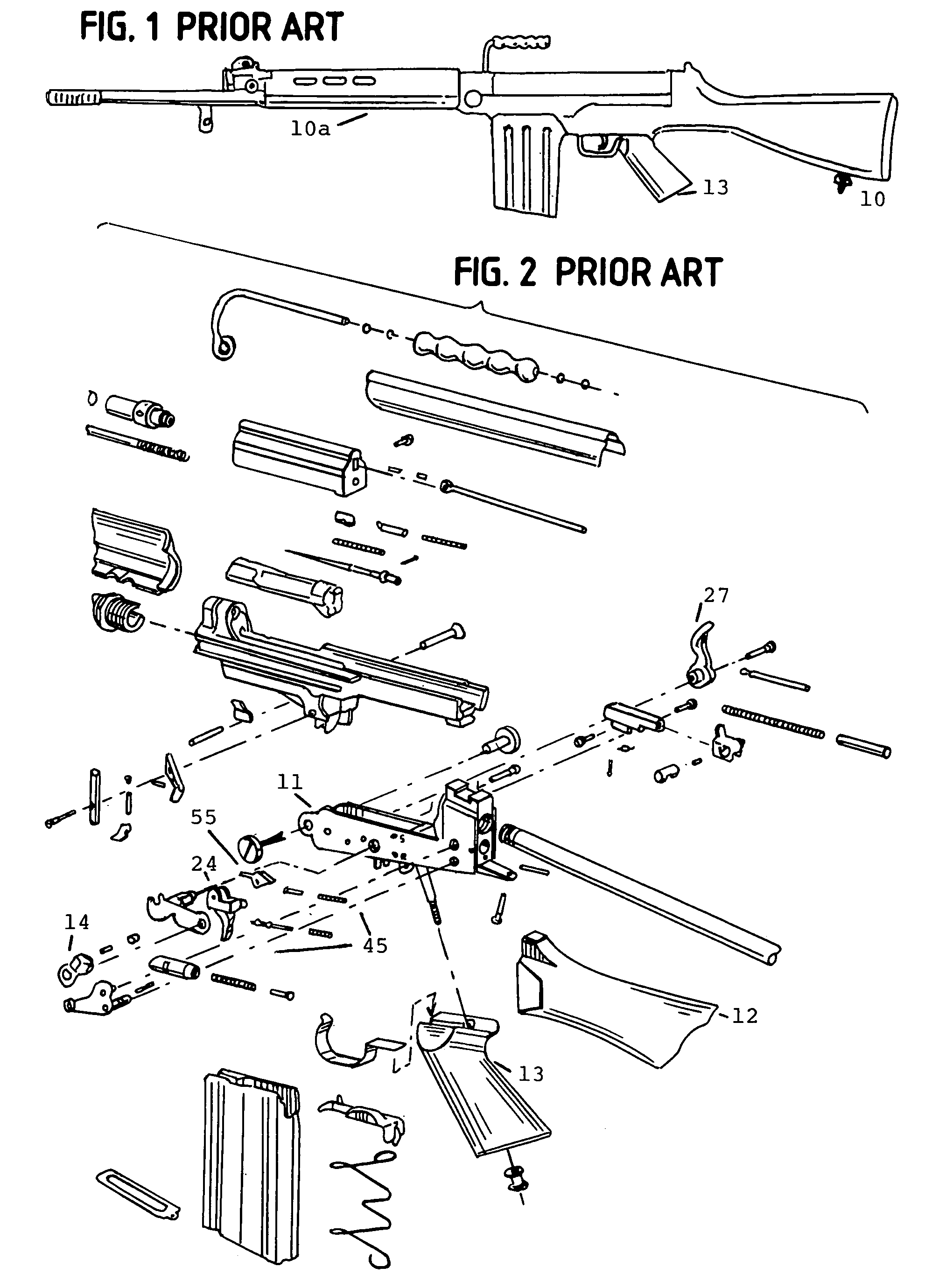
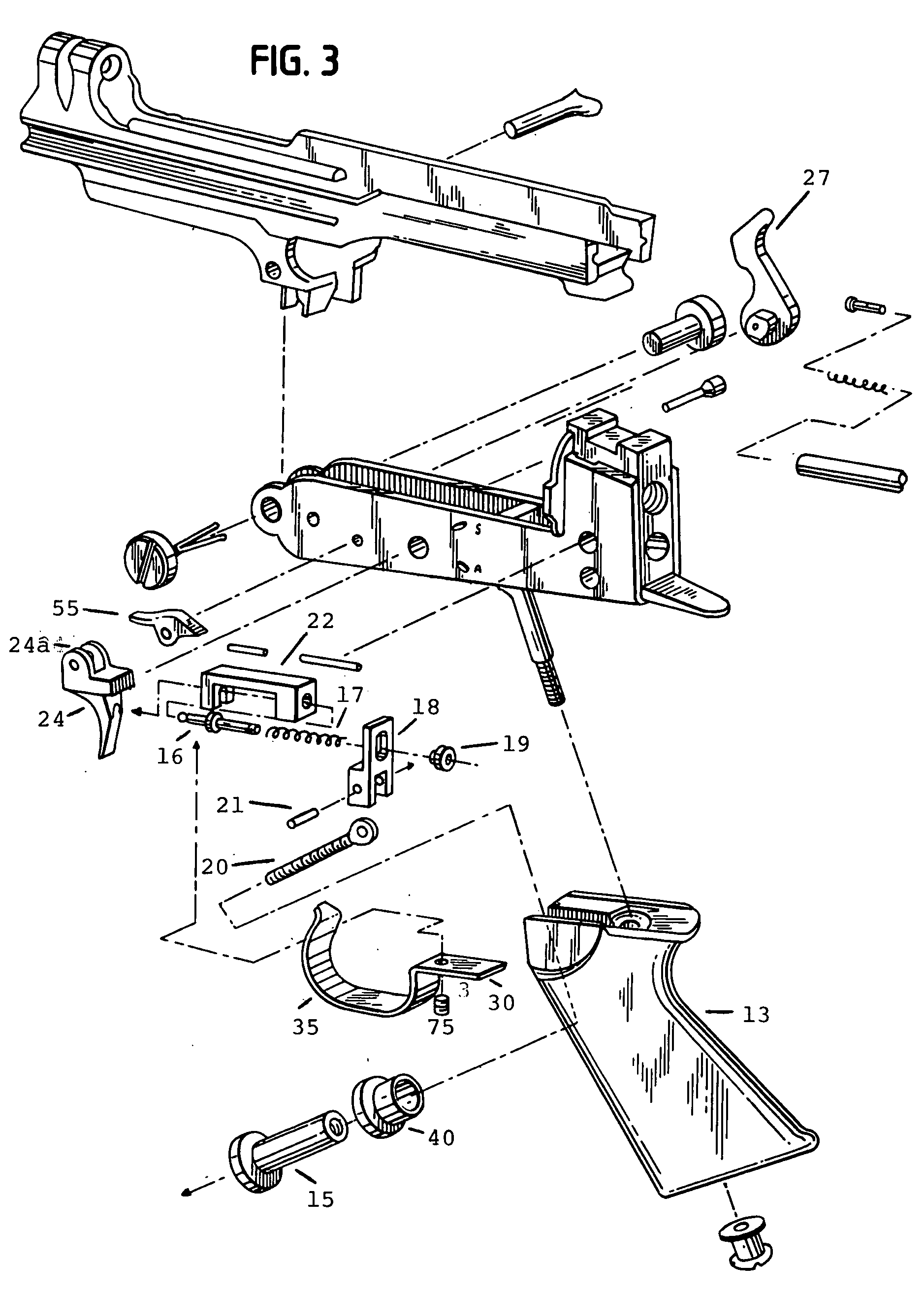
[0030]With reference to the accompanying drawings, the set trigger assembly 50 embodying the present invention is found in the grip 13 of the FAL rifle 10 as shown. The entire rifle 10 has a the receiver lower 11 . The receiver lower 11 is attached to the butt 12. In the receiver lower 11 there is a safety lever 14, housed in the receiver lower 11 and the trigger 24 and the grip 13. Housed within the grip 13 is the trigger assembly 45 and the set trigger assembly 50, to be described hereafter. The trigger assembly 45 is made up of the trigger 24 and resisting the trigger is the screw or return spring plunger 16 that is mounted with the spring or return spring plunger spring 17. The plunger 16 going through the spring 17 is mounted to the receiver lower 11 through the bracket or return spring plunger guide 22. This set trigger assembly 50 attaches to the trigger assembly 45 at the rear of the plunger 16. The plunger 16 fits through the set trigger attaching plate or trigger cam lever...


PUM


Abstract

A set trigger assembly that enables a user of a firearm with a trigger, return spring plunger, and a return spring plunger spring to modify the trigger mechanism on-demand to reduce the trigger pressure required to fire the firearm by enabling the user to retract the return spring plunger and then return the return spring plunger to its initial position by insertion of a lever which is used to apply force to a return spring plunger so as to force the return spring plunger away from the trigger.

Description

[0001]This application claims priority from United States Provisional Patent Application Ser. No. 60 / 657,793 filed 28 Feb. 2006. This invention relates to a set trigger for a firearm that is particularly useful in allowing target shooting and other shooting environments requiring great accuracy.BACKGROUND AND SUMMARY OF THE INVENTION[0002]Typically, a Fusil Automatique Leger rifle, commonly known as a FAL rifle, has a single trigger that cannot be adjusted. Typically, a FAL requires eight pounds to fifteen pounds of pressure on the trigger to fire the rifle. If the trigger is set with too much resistance, then a person firing the rifle would likely move the rifle in applying sufficient pressure to the trigger when firing the rifle. The result of inadvertent movement is that the person would shoot less accurately. This problem is particularly serious where accuracy is key such as in competition shooting and sniper shooting.[0003]Conversely, if the trigger is adjusted such that resist...

Claims


Application Information

Patent Timeline
Patent Type & Authority Applications(United States)
IPC IPC(8): F41A19/10
CPCF41A19/17F41A19/16
Inventor WILLIAMS, DENNYABRAHAM, DICK
Owner DSA AN ILLINOIS CORP
Why Eureka
Try Eureka