
Frictional rope control device with on the fly friction adjustment

a technology of friction adjustment and control device, which is applied in the direction of life-saving devices and building rescue, etc., can solve the problem of insufficient total friction of the rappel device, and achieve the effect of safe us

Active Publication Date: 2016-07-28
GALYAN RANDALL LUKE
View PDF30 Cites 5 Cited by
  • Summary
  • Abstract
  • Description
  • Claims
  • Application Information

AI Technical Summary

Benefits of technology

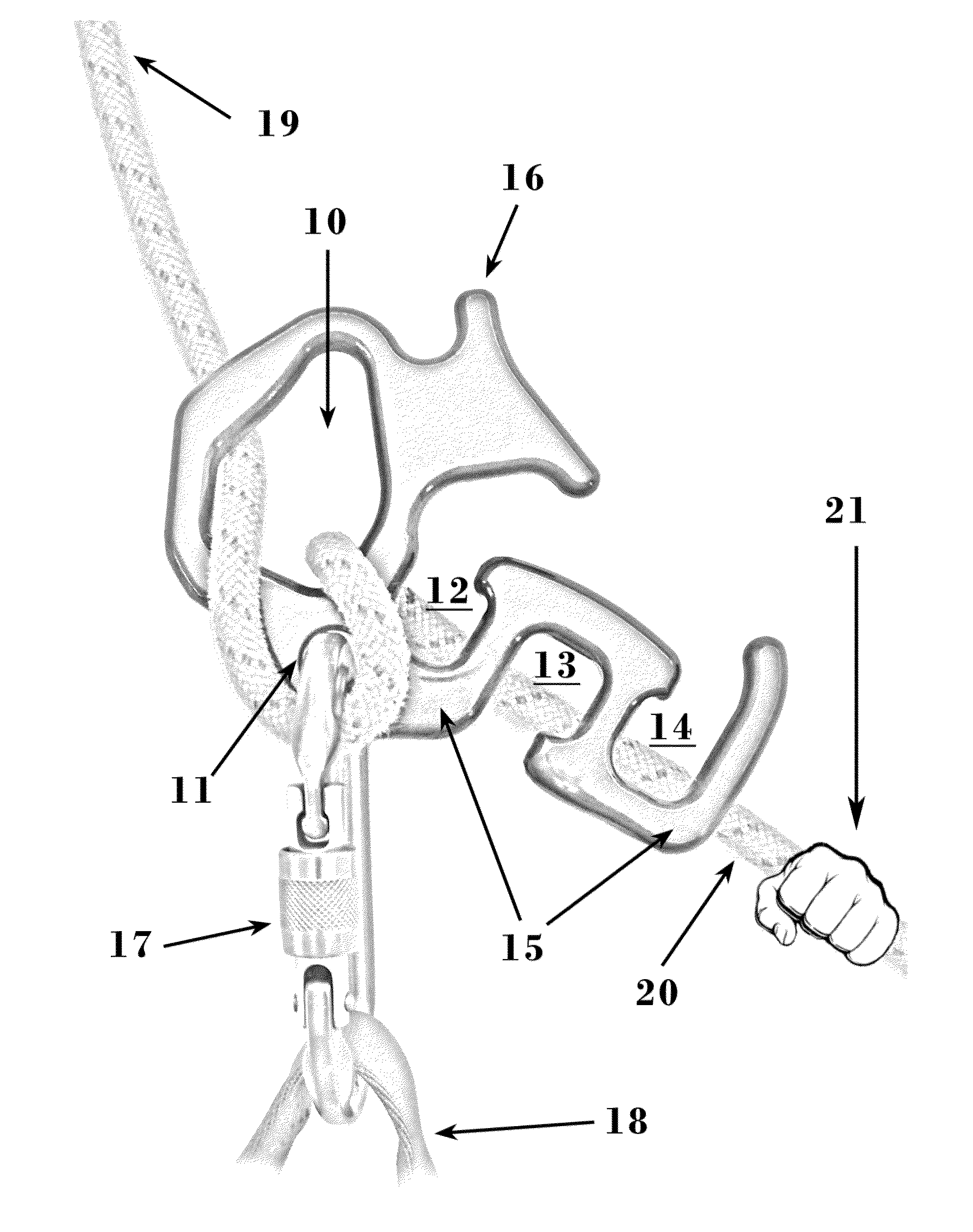
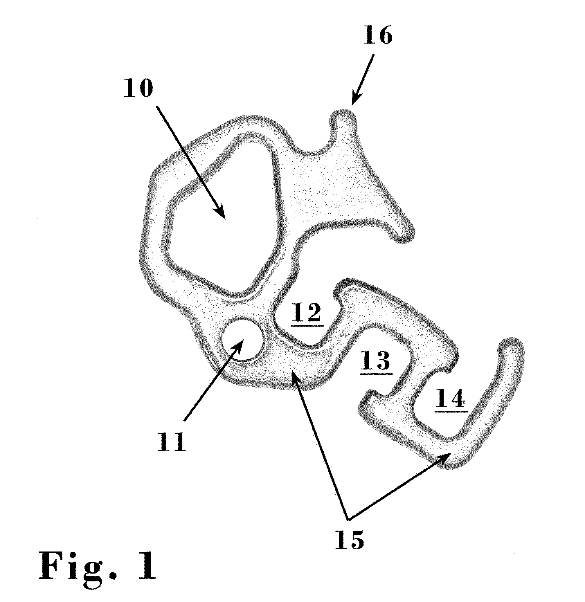
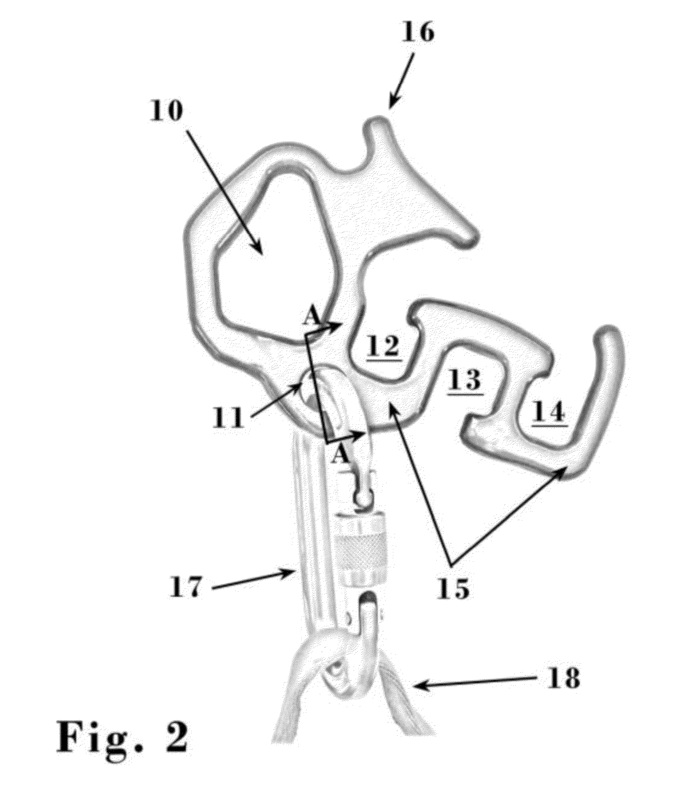
The present invention is for a rappel device that can safely be used with single or double ropes of various sizes and constructions. It allows users to adjust the friction through usable increments while carrying a load. The device has a wide range of friction, and a tab and gland can be used to secure the rope in place. Overall, the invention provides a reliable and versatile tool for rappel activities.

Problems solved by technology

Many people find their rappel devices offer insufficient total friction.
Problem 2: Few rappel devices provide a wide enough range of friction capable of meeting the needs of large and small people.
Problem 3: With current rappel devices large people prefer to rappel double strand rather than single strand on thin rope due to insufficient friction resulting from the thin rope.

Method used


Image

  • Frictional rope control device with on the fly friction adjustment
  • Frictional rope control device with on the fly friction adjustment
  • Frictional rope control device with on the fly friction adjustment

Examples


Embodiment Construction

[0031]It is advantageous to define several terms before describing the invention. It should be appreciated that the following definitions are used throughout the application.

[0032]Where the definition of terms departs from the commonly used meaning of the term, applicant intends to utilize the definitions provided below, unless specifically indicated.

DEFINITIONS

[0033]For the purposes of the present invention, directional terms such as “up”, “down”, “top”, “bottom”, “above”, “below”, “left”, “right”, “horizontal”, “vertical”, etc. are merely used for convenience in describing the various embodiments of the present invention. The embodiments of the present invention may be oriented in various ways.

[0034]For the purposes of the present invention, the term “rappel device” refers to a device which allows rope to be directed through the device to frictionally control movement of a load relative to an anchor point which may take the form of a sliding descent down the rope, lowering a load ...


PUM


Abstract

A rappelling device that frictionally controls rope flow, thereby allowing adjustable control of a load relative to an anchor is disclosed. For example, a coupling link, such as a carabiner, is clipped into a small hole, a bight of rope is pushed through a separate large hole, and then the rope is clipped into the carabiner. A user may use the rappelling device to increase the friction while the rope is weighted by weaving the rope through one or more openings on the device. In doing so, the user does not need to feed the end of the rope through the one or more openings. The rappelling device provides incremental adjustment of friction while the rope is weighted. Additionally, a gland cut into the inner circumference of the small hole may be added to grip and limit axial movement of the carabiner.

Description

BACKGROUND OF THE INVENTION[0001]Ropes are an essential part of a wide variety of professional and recreational activities where rope work is required. The need often exists for a user to use a rope to control the movement of a load relative to an anchor point.[0002]The construction and use of general purpose rope rigging devices such as tackle blocks, belay devices, ascenders, carabiners, and pulleys are well-known. In addition, numerous rigging devices have been developed specifically to facilitate the use of ropes to frictionally control movement of a load relative to an anchor point.[0003]Various improvements have been made with the addition of various tabs, horns or protrusions to manipulate rope flow and vary the amount of friction. Though such devices have achieved considerable popularity and commercial success, there has been a continuing need for improvement. New rope materials and construction techniques have produced ropes with less friction resulting in an increased need...

Claims


Application Information

Patent Timeline
Patent Type & Authority Applications(United States)
IPC IPC(8): A62B1/08
CPCA62B1/08A62B1/14
Inventor GALYAN, RANDALL LUKE
Owner GALYAN RANDALL LUKE
Learn More