
System for Improving a Logic Circuit and Associated Methods

a logic circuit and logic circuit technology, applied in the field of resistive-capacitive delay, can solve the problems of parasitic properties, adversely affecting timing, and increasing frequency, and achieve the effect of improving logic blocks and reducing resistive-capacitive delays

Inactive Publication Date: 2009-04-23
GLOBALFOUNDRIES INC
View PDF12 Cites 15 Cited by
  • Summary
  • Abstract
  • Description
  • Claims
  • Application Information

AI Technical Summary

Benefits of technology

[0010]In view of the foregoing background, it is therefore an object of the invention to reduce the resistive-capacitive (RC) delay through a logic circuit.
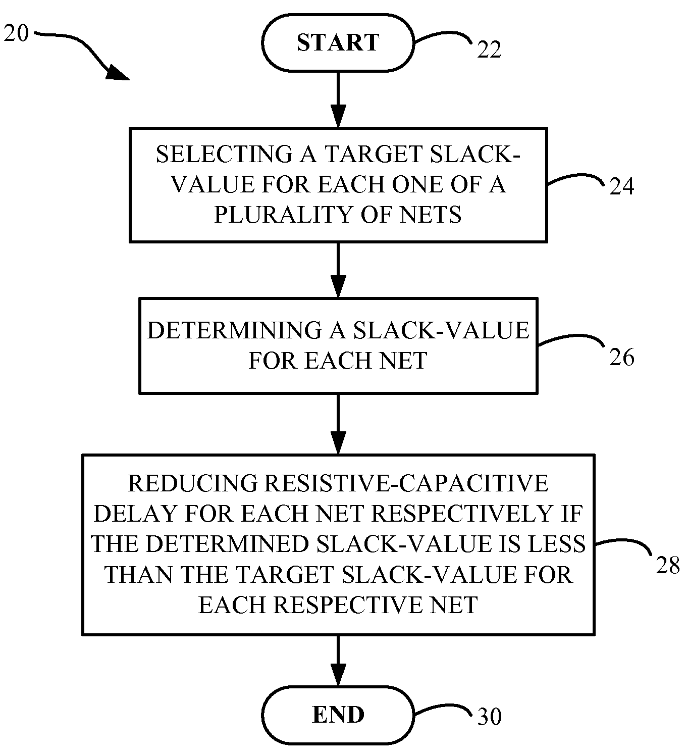
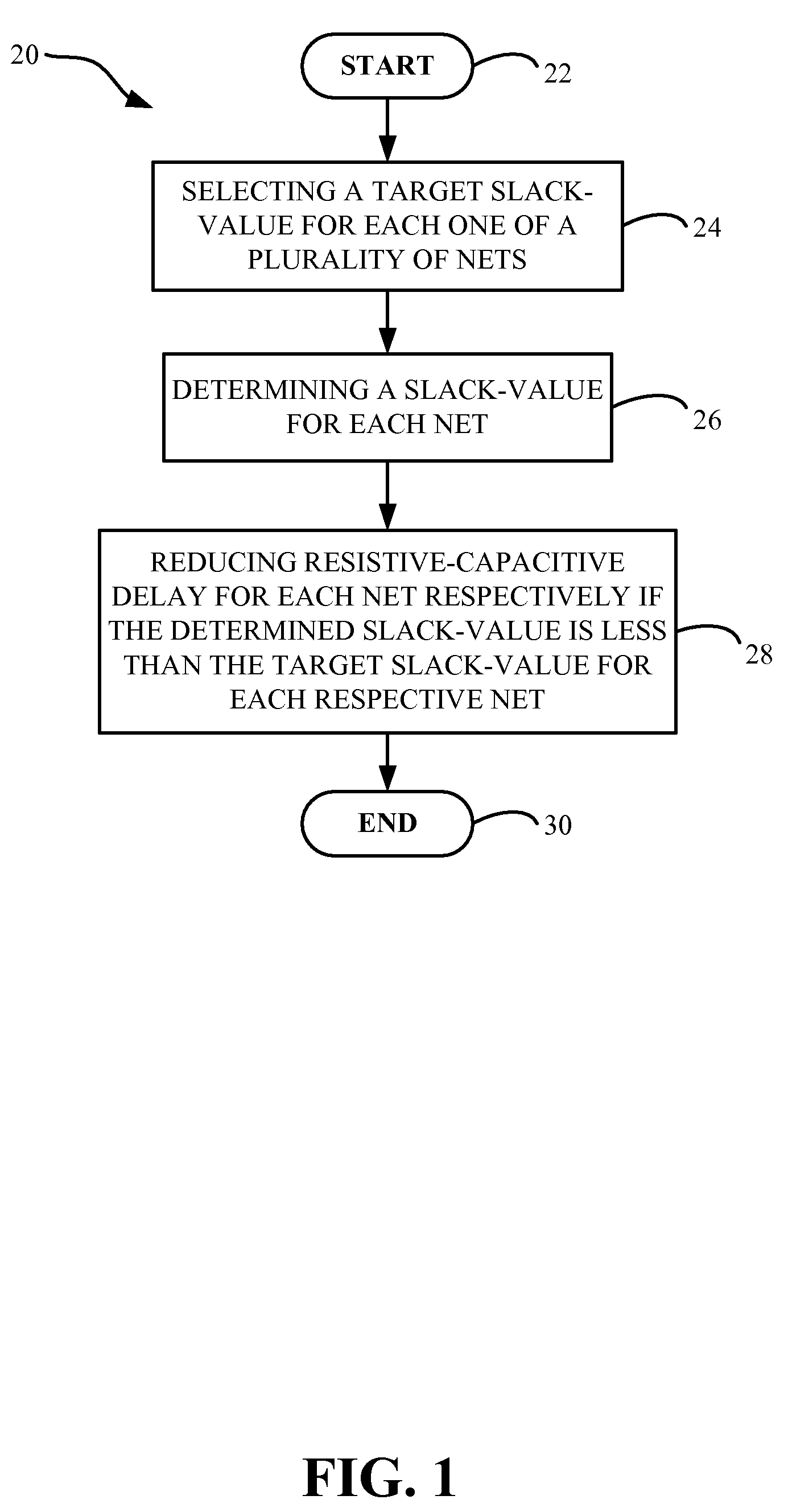
[0012]The logic circuit analyzer may determine a slack-value for each net. In addition, the logic circuit analyzer may selectively reduce resistive-capacitive delay for each net respectively if the determined slack-value is less than the target slack-value for each respective net.
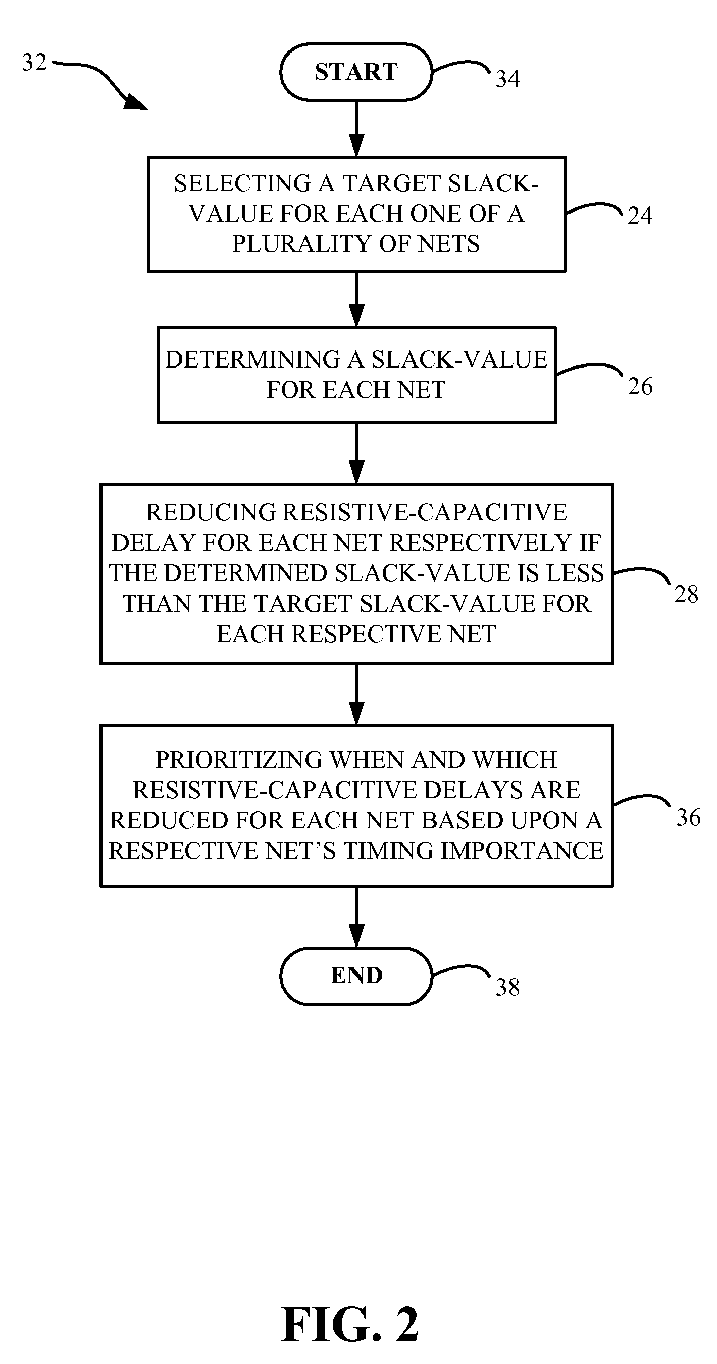
[0014]Another aspect of the invention is a method to improve a logic block. The method may include selecting a target slack-value for each one of a plurality of nets, and determining a slack-value for each net. The method may also include reducing resistive-capacitive delay for each net respectively if the determined slack-value is less than the target slack-value for each respective net.
[0015]The method may further include prioritizing the reducing of any resistive-capacitive delay for each net based upon a respective net's timing importance. The method may additionally include replacing existing layer assignments and wire code assignments for each net with updated layer assignments and wire code assignments in order for each net to approach its respective target slack-value.
[0016]The method may also include changing buffers within important timing paths for each net to low threshold voltage buffers if the determined slack-value is less than the target slack-value for a respective net. The method may further include updating the layer assignments and wire code assignments for each net are based upon at least one of downgrading and upgrading of the existing layer assignments and wire code assignments to help a respective net approach its target slack-value. The updated layer assignments and wire code assignments for each net may aid in correcting slew violations for each respective net.
[0017]The method may also include re-buffering each net based upon respective updated layer assignments and wire code assignments. Additionally, each re-buffered net may aid in correcting slew violations for each respective net.

Problems solved by technology

This adversely affects the timing by adding resistive and capacitive delay to the wires.
These properties, also known as parasitics, also get worse with increasing frequency.

Method used


Image

  • System for Improving a Logic Circuit and Associated Methods
  • System for Improving a Logic Circuit and Associated Methods
  • System for Improving a Logic Circuit and Associated Methods

Examples


Embodiment Construction

[0026]The invention will now be described more fully hereinafter with reference to the accompanying drawings, in which preferred embodiments of the invention are shown. This invention may, however, be embodied in many different forms and should not be construed as limited to the embodiments set forth herein. Rather, these embodiments are provided so that this disclosure will be thorough and complete, and will fully convey the scope of the invention to those skilled in the art. Like numbers refer to like elements throughout, and prime notation and multiple prime notation is used to indicate similar elements in alternative embodiments.

[0027]As will be appreciated by one skilled in the art, the invention may be embodied as a method, system, or computer program product. Furthermore, the invention may take the form of a computer program product on a computer-usable storage medium having computer-usable program code embodied in the medium.

[0028]Any suitable computer usable or computer rea...


PUM


Abstract

A system for improving a logic circuit may include a processor, and a logic circuit analyzer in communication with the processor to model a plurality of nets. The system may also include an interface in communication with the logic circuit analyzer to select a target slack-value for each one of the plurality of nets. The logic circuit analyzer may determine a slack-value for each net. In addition, the logic circuit analyzer may selectively reduce resistive-capacitive delay for each net respectively if the determined slack-value is less than the target slack-value for each respective net.

Description

RELATED APPLICATION[0001]This application contains subject matter related to a co-pending U.S. patent application Ser. No. 11 / 334,256 filed Jan. 18, 2006 and entitled “VLSI Timing Optimization with Interleaved Buffer Insertion and Wire Sizing Stages”, the entire subject matter of which is incorporated herein by reference in its entirety. The aforementioned application is assigned to the same assignee as this application, International Business Machines Corporation of Armonk, N.Y.FIELD OF THE INVENTION[0002]The invention relates generally to the field of custom processor design, and in particular to the area of resistive-capacitive delay.BACKGROUND OF THE INVENTION[0003]Very large scale integrated (VLSI) circuit cards are usually the core components in today's highly complex electronic circuitry and / or logic circuitry found in mainframe servers. These circuit cards typically are packaged as multiple chips fabricated on a single card assembly or module, and are inherently referred to ...

Claims


Application Information

Patent Timeline
IPC IPC(8): G06F17/50
CPCG06F17/505G06F17/5031G06F30/3312G06F30/327G06F30/3315
Inventor CARNEY, CHRISTOPHERNEVES, JOSE LUISPLUCHINO, BIAGIO
Owner GLOBALFOUNDRIES INC
Learn More