
Method and Device for the Assessment of Fluid Collection Networks

a fluid collection and flow rate technology, applied in the direction of liquid/fluent solid measurement, volume metering, instruments, etc., can solve the problems of untreated wastewater entering the environment, restrictions and blockages in the sewer system, and the source of significant water pollution in the treatment facility decreasingly, so as to achieve low cost and simple device use.

Inactive Publication Date: 2009-04-23
SAYLOR DAVID J
View PDF93 Cites 54 Cited by
  • Summary
  • Abstract
  • Description
  • Claims
  • Application Information

AI Technical Summary

Benefits of technology

[0034]An improved device and method for analyzing sewer systems maintains the benefits of traditional sewer analysis systems, while achieving the important objective of providing a low cost, simple, and easy to use device and method for monitoring fluid level and flow rates at multiple locations in a sewer system.
[0037]A low usage cost of sewage flow and level measuring and monitoring device according to the invention is thereby achieved by a low cost of accelerometers and pressure sensors, a small size and weight of the monitoring device, an easy replacement of components, and by ease of installing such device into a sewer system manhole. The device and method also improve safety compared with conventional method because personnel are not required to enter the manhole during installation of device. Additionally, in one variation, the pole that supports the bendable tube may be formed to be collapsible or segmented to decrease the space required for storage or transport of the device of the present invention.

Problems solved by technology

However, in recent years, the technology for treating wastewater has largely matured to the point that treatment facilities are decreasingly the source of significant water pollution.
In either case, untreated wastewater can overflow from the system into the environment.
The primary causes are restrictions and blockages in the sewer system, most often caused by the accumulation of debris, roots and / or grease in a sewer pipe.
In wet weather conditions, storm water runoff may overwhelm the capacity of a combined sanitary sewer and storm water system, and cause the system to overflow.
Studies have shown, however, that restrictions and blockages are the primary causes of overflows, not a lack of capacity in the system.
Thus, simply adding additional capacity leads to piping systems that are underutilized and more expensive than necessary to serve the sanitary needs of the community.
Even if the infiltration does not lead to a system overflow, infiltration and inflow of storm water into a sanitary sewer system leads to increased costs because the storm water inflow must then be treated along with the untreated sewage.
Restrictions, infiltrations and inflows lead to increased costs and potential environmental problems, and an SSO may result in untreated sewage being released into the environment or backing up into residential basements.
However, because these pipes are typically underground, the infiltration point is difficult if not impossible to locate and detect by visual inspection during a wet weather event.
Although the location of an overflow may be obvious, the source of the extra water that is actually causing the overflow may be a mystery.
Also, in most cases, the only evidence of infiltration is the increased burden on treatment facilities during a wet weather event.
Such flow measurement studies, however, are difficult and expensive to administer, in addition to being difficult to schedule due to the unpredictability of the weather.
Some larger authorities have employed complex and expensive evaluation methods to identify potential causes of sewer infiltration and SSO's.
These methods often include the use of expensive devices for monitoring flow at different points in the system and the employment of personnel and / or consultants to collect and analyze data from the flow monitoring devices.
Although inexpensive compared to other measurement techniques, these types of devices necessarily obstruct the fluid flow.
In addition, these types of devices are not well suited for certain applications because the measurement device cannot be easily inserted and secured in the fluid flow.
Although more precise and reliable, these types of devices are typically very expensive, limiting their application.
Also, due to limitations of the technology, these devices are often not well suited for measuring irregular flows that may include solids.
These types of flow meters are also disadvantageous for many applications because they are difficult to install, calibrate, and operate.
Although these and other devices have been developed that measure fluid flow based on the measurement of vortices or the oscillation of an object in a fluid flow, such fluid flow measurement technique has not seen widespread application.
Specifically, many conventional sewage flow meters and associated techniques are often beyond the financial capacity and skill set of small and medium sized sanitary system authorities.
Also, because of the cost and complexity of these evaluation methods, a complete review of the entire sanitary system is typically not performed by sanitary system authorities capable of affording such techniques and software.
Thus, although general problem areas in the system may be identified, specific pipe restrictions and blockages may be missed.
Due to the cost of employing data collection personnel and consultants, the review and analysis of most sanitary sewer systems is typically short lived, and usually only performed in response to a specific problem or overflow.
Prior art evaluation techniques are typically project-based, specific to a particular problem and not designed for ongoing assessment of the collection network.
The resultant data is typically not incorporated into the ongoing operation and maintenance procedures of the authority, and is therefore not helpful in identifying and solving future problems in the system.
This critical next step can be expensive and difficult to conduct.
If the study merely identifies large portions of the system that have infiltration, the study is essentially useless because these large portions must still be inspected.
Those of skill in the art have developed complex methodologies and expensive solutions to provide greater precision in identifying the potential location of infiltration and inflow.
Although this solution may be cost effective because it decreases the cost of the next step in the process, this solution is nonetheless very expensive and beyond the financial capabilities of many small and medium sized sanitary sewer system authorities.
Sewage flow measurement devices are expensive, and the additional personnel required to monitor and measure additional points in the system also increases the expense of the sewage flow measurement study.
These techniques often require extended on-sight evaluations by consultants, which further increases the cost.
Because the evaluation of sanitary sewer systems has historically been project-based and in response to a specific problem or overflow, little attention has been paid to the ongoing maintenance and upkeep of the system.
However, sewer system assets that are not regularly maintained deteriorate faster, leading to higher replacement and emergency response costs.
When a sewer system is regularly maintained, its lifetime can be increased and maintenance costs distributed over the lifetime of the system.

Method used


Image

  • Method and Device for the Assessment of Fluid Collection Networks
  • Method and Device for the Assessment of Fluid Collection Networks
  • Method and Device for the Assessment of Fluid Collection Networks

Examples


Embodiment Construction

[0118]The present invention may be used with any type of fluid collection network and is particularly suited for monitoring sanitary and storm sewer systems. However, for descriptive purposes, the present invention will be described in use with sanitary and storm sewer systems.

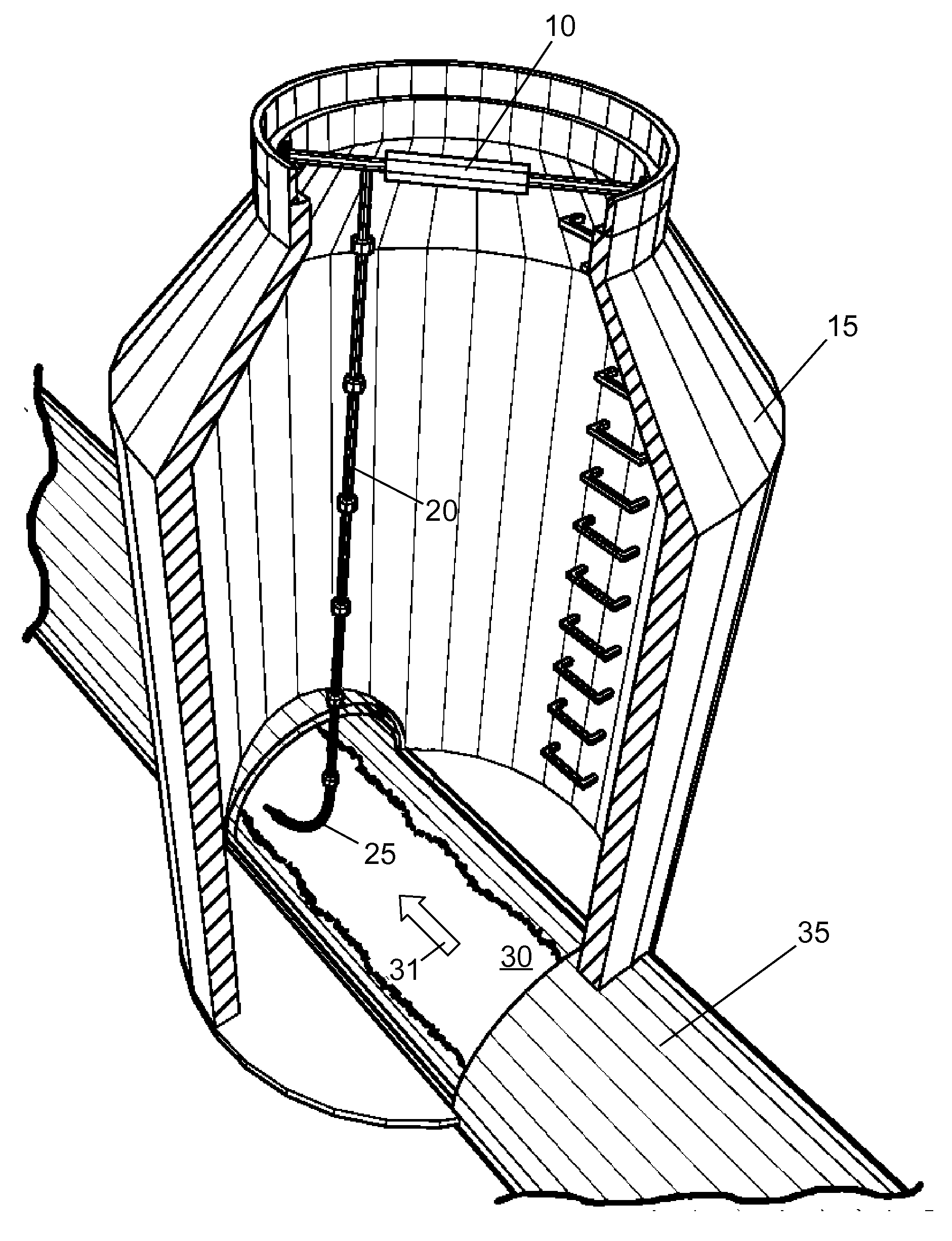
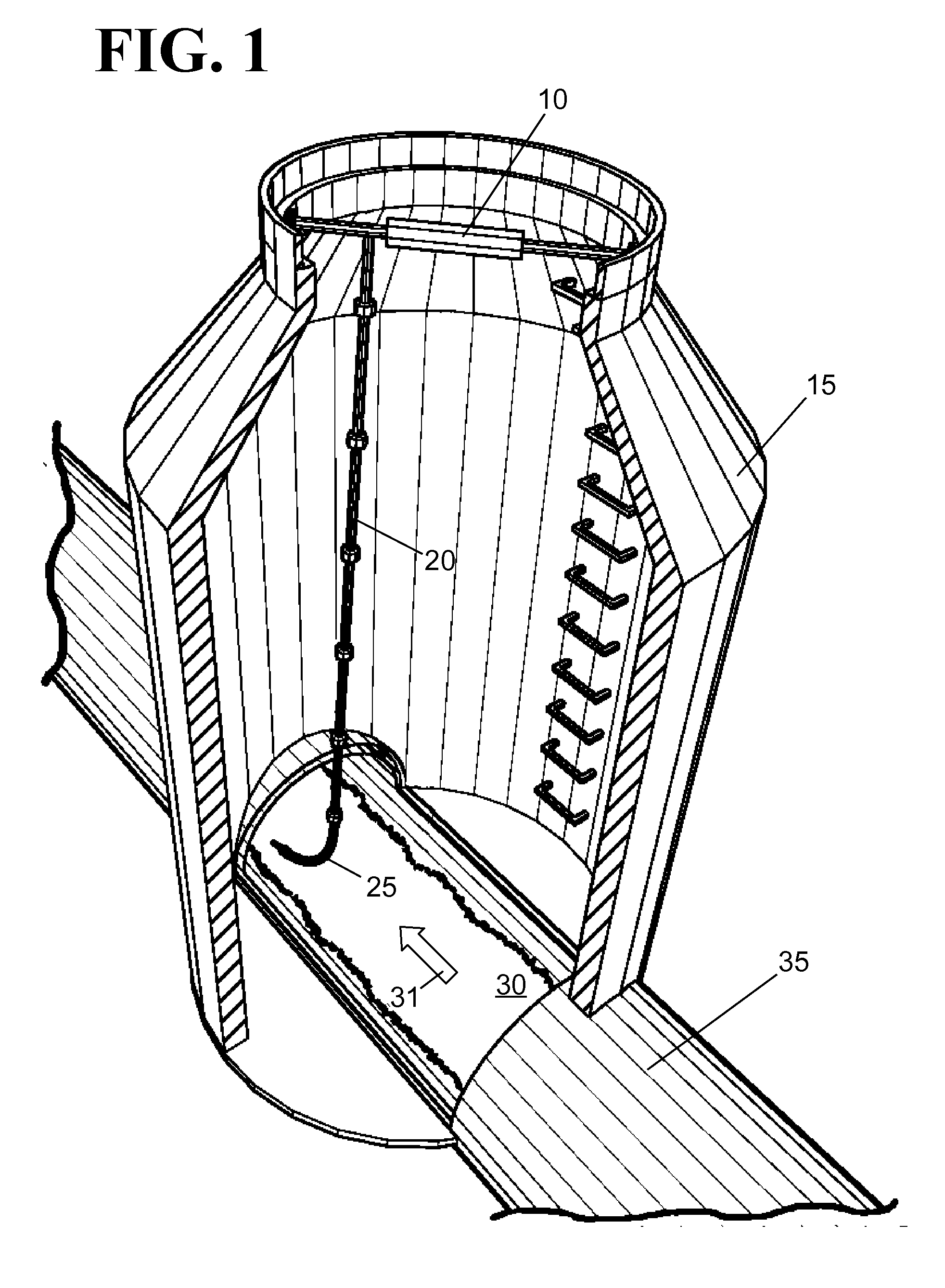
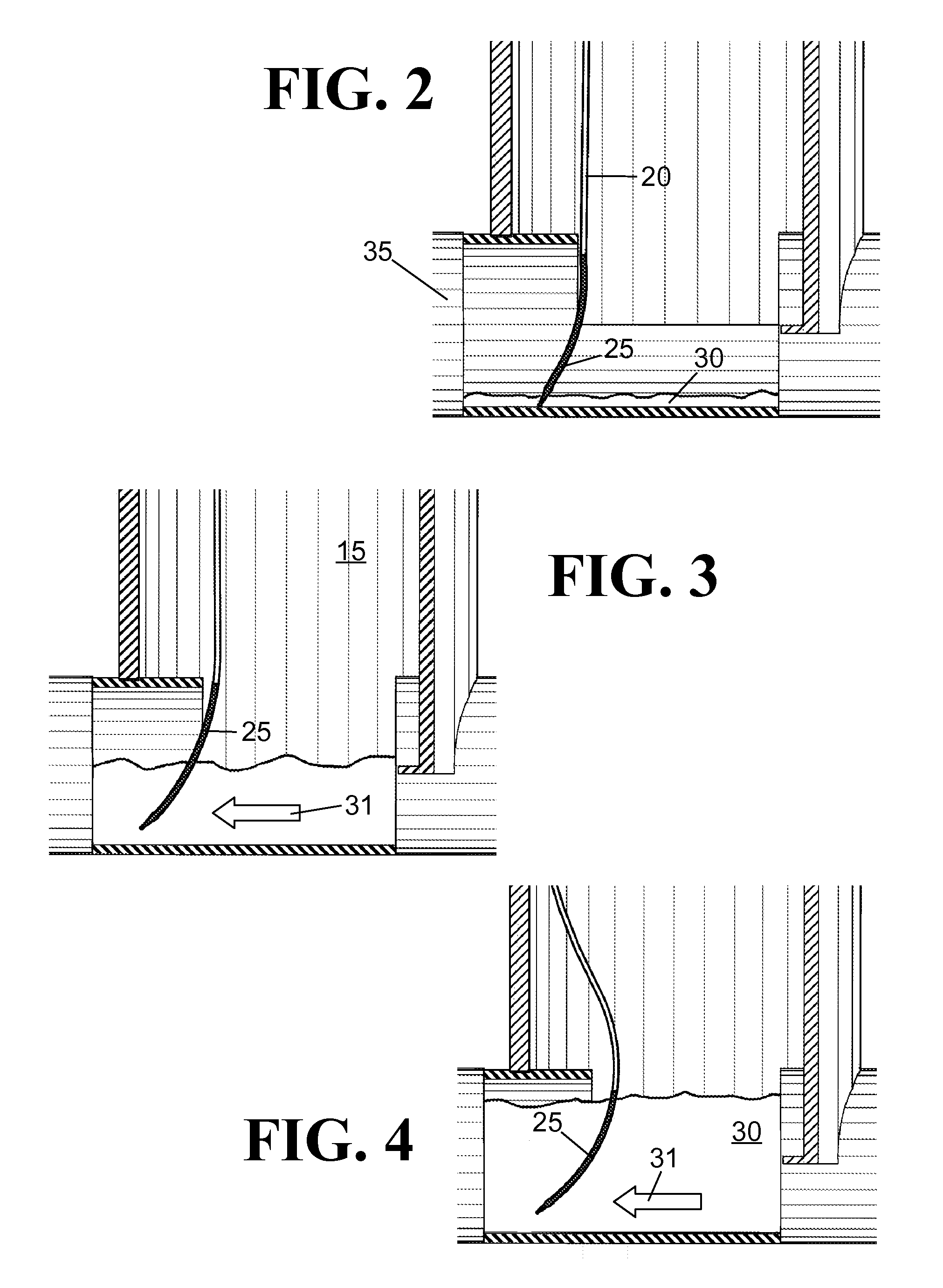
[0119]FIG. 1 shows a perspective view of a monitoring device comprising a securing mechanism in the form of an expansion device 10 contacting near the top of a manhole 15, a vertically oriented spanning mechanism in the form of a pole 20 attached to the expansion device and substantially spanning the height of the manhole, and a flow meter 25 in the sewer flow 30 moving in a flow direction 31 inside of a sewer pipe 35. The flow meter 25 has a data acquisition device with an accelerometer and pressure monitor that records the inclination, oscillations, and pressure exerted upon the flow meter. The segmented pole 20 is adjustable so that the flow meter 25 may be positioned above the sewer pipe bottom, while stil...


PUM


Abstract

The improved monitoring device includes a data acquisition device with an accelerometer inside a bendable tube. One end of the tube is connected to a pole that may be secured to the top of a sewer manhole, while the other end is submerged in a fluid flow. The tilt, oscillations, and pressure exerted upon the tube due to fluid flow are measured and recorded. An improved method includes installing several monitoring devices into sewer system manholes, recording fluid level and flow, reading the recorded data, and displaying the data in chart or map form. Data may be displayed in two or three dimensional maps that may be overlaid with information of topography, street maps, and single or multiple sewer systems. Data displayed on the maps may include fluid flow rates, fluid levels, derivatives and integrals of flow rates, and differences in fluid levels or flow between monitoring devices.

Description

CROSS-REFERENCE TO COPENDING APPLICATION[0001]This application claims the benefit of U.S. Provisional Patent Application Ser. No. 61 / 000,050, entitled “Method and Device for the Assessment of Fluid Collection Networks” filed Oct. 23, 2007, which is incorporated herein by reference in its entirety.FIELD OF THE INVENTION[0002]The present invention relates generally to a device and method for testing flow rates in a liquid system, and more particularly to a device and method for continuously monitoring flow rates in a sewer system.BACKGROUND OF THE INVENTION[0003]To prevent water pollution in furtherance of the goals of the Clean Water Act, regulations and enforcement actions have historically focused on the output of wastewater treatment facilities. However, in recent years, the technology for treating wastewater has largely matured to the point that treatment facilities are decreasingly the source of significant water pollution. To further eliminate potential water pollution, the Uni...

Claims


Application Information

Patent Timeline
IPC IPC(8): G01F1/00
CPCG01D9/005G01D21/00G01F1/20G01F1/32G01F23/00G01F1/684G01F15/063G01F15/0755G01F1/68
Inventor SAYLOR, DAVID J.
Owner SAYLOR DAVID J
Learn More