
System having wireless implantable sensor

a sensor and wireless technology, applied in the field of implantable sensing devices, can solve the problems of reducing the overall size of the implant, complicating the implementation of flow rate sensors and chemical sensors,

Active Publication Date: 2009-04-23
UIM PRESSURE IMPLANT INC
View PDF45 Cites 58 Cited by
  • Summary
  • Abstract
  • Description
  • Claims
  • Application Information

AI Technical Summary

Benefits of technology

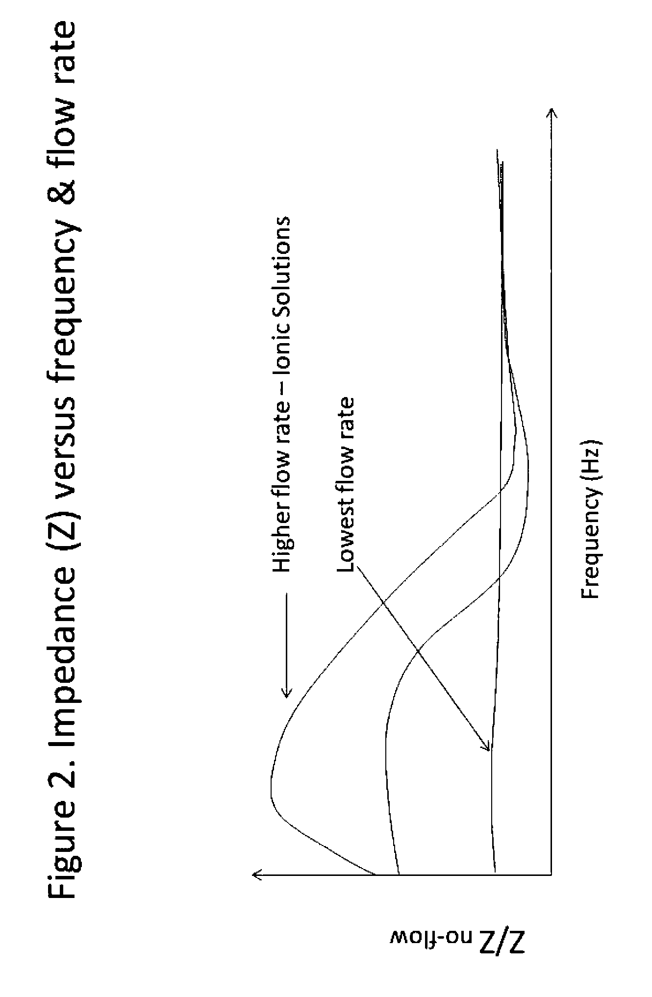
[0004]The present invention provides an implantable sensor, sensing system, and sensing method suitable for sensing flow rates, chemical concentrations, conductivity, and pH of various fluids within or introduced into a human body by measuring charge-based parameters associated with ionic solutions in a manner that minimizes the power requirements of the sensor.

Problems solved by technology

The necessity for implantable sensors to operate at very low currents and power levels, as well as the desire to minimize the overall size of the implant, complicates the implementation of flow rate sensors and chemical sensors that rely on such conventional sensing devices as hot-wire anemometers, piezoresistive sensors, and other flow meters with moving parts.

Method used


Image

  • System having wireless implantable sensor
  • System having wireless implantable sensor
  • System having wireless implantable sensor

Examples


Embodiment Construction

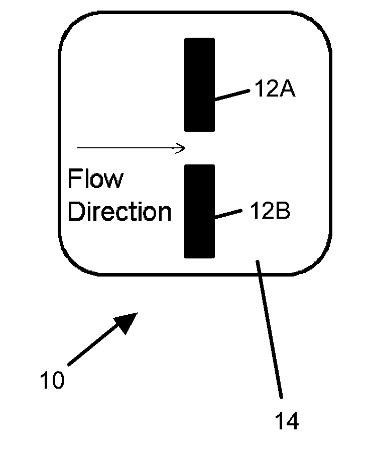
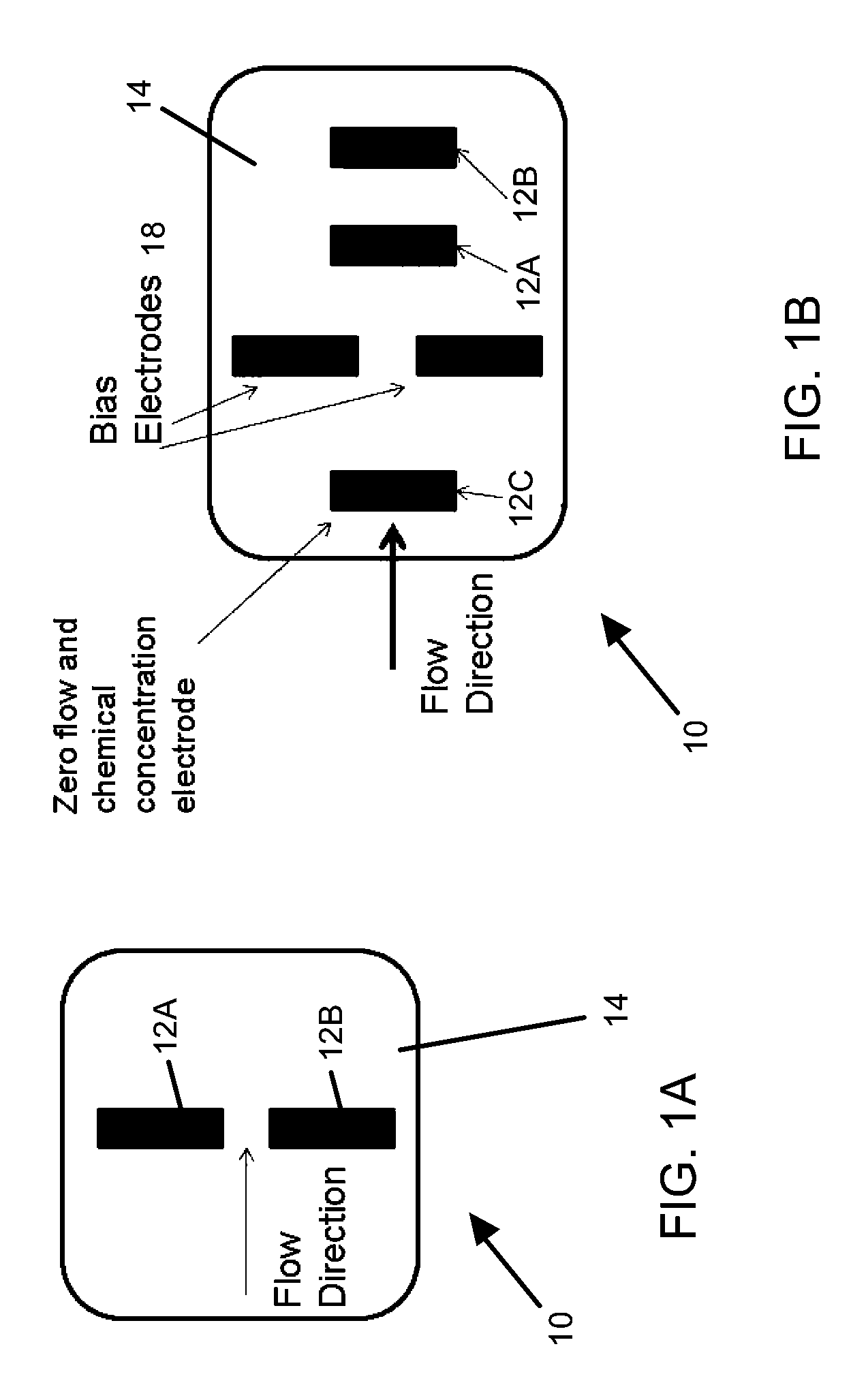
[0017]FIGS. 1A and 1B show examples of arrangements of sense electrodes 12 for sensing flow rates, chemical concentration, or another charge-based parameter of an ionic fluid in accordance with embodiments of this invention. In each of FIGS. 1A and 1B, a pair of sense electrodes 12 (designated as 12A and 12B) is shown on an outer surface 14 of a sensor 10. The electrodes 12A-B form a sensing element adapted to sense charged-based parameters of an ionic fluid using impedance measurements that are based on known principles, for example, as described in H. Ayliffe and R. Rabbit, “An electric impedance based MEMS flow sensor for ionic solutions,” Meas. Sci. Technol. 14, pp. 1321-1327 (2003.). An electric current, typically about 0.1 milliamps or less alternating current at a frequency of about 100 Hz to about 100 kHz, is applied across the paired electrodes 12A-B. The electrodes 12A-B are sufficiently close together to insure that charged ions remain separated, enabling an impedance or ...


PUM


Abstract

A system for monitoring a charge-based physiological parameter within an internal organ of a living body, and a sensor adapted to be implanted in the living body and an organ therein. The sensor includes sensing elements adapted to sense the charge-based physiological parameter within the organ, and the sensing elements include at least first and second sensing elements that are electrically conductive, aligned, spaced apart and exposed at the exterior of the sensor. The sensor further includes a device for passing an alternating current from the first to the second sensing elements through an ionic solution contacting the sensing elements. The sensor also includes a device for generating a signal corresponding to the impedance of the ionic solution based on the alternating current.

Description

CROSS REFERENCE TO RELATED APPLICATIONS[0001]This application claims the benefit of U.S. Provisional Application No. 60 / 999,315, filed Oct. 17, 2007, the contents of which are incorporated herein by reference.BACKGROUND OF THE INVENTION[0002]The present invention generally relates to implantable sensing devices, and more particularly to an implantable sensing device equipped with electrodes to provide a flow and / or chemical sensing capability.[0003]Wireless devices such as pressure sensors have been implanted and used to monitor heart, brain, bladder and ocular function. With this technology, capacitive pressure sensors are often used, by which changes in pressure cause a corresponding change in the capacitance of an implanted capacitor (tuning capacitor). The change in capacitance can be sensed, for example, by sensing a change in the resonant frequency of a tank or other circuit coupled to the implanted capacitor. The circuit can be implanted with the capacitor in the patient, and...

Claims


Application Information

Patent Timeline
Patent Type & Authority Applications(United States)
IPC IPC(8): A61B5/05
CPCA61B5/0031A61B5/0537A61B5/6882A61B5/6864A61B5/14539
Inventor NAJAFI, NADERSPARKS, DOUGLAS RAY
Owner UIM PRESSURE IMPLANT INC
Learn More