Red phosphorescent compounds and organic electroluminescent devices using the same
a technology of red phosphorescent compounds and organic electroluminescent devices, which is applied in the direction of discharge tube luminescnet screens, other domestic articles, natural mineral layered products, etc., can solve the problems of limited viewing angle and inability to use backlight, and achieve good red color purity, long life, and high luminescence efficiency
- Summary
- Abstract
- Description
- Claims
- Application Information
AI Technical Summary
Benefits of technology
Problems solved by technology
Method used
Image
Examples
example 1
Example 1-(1)
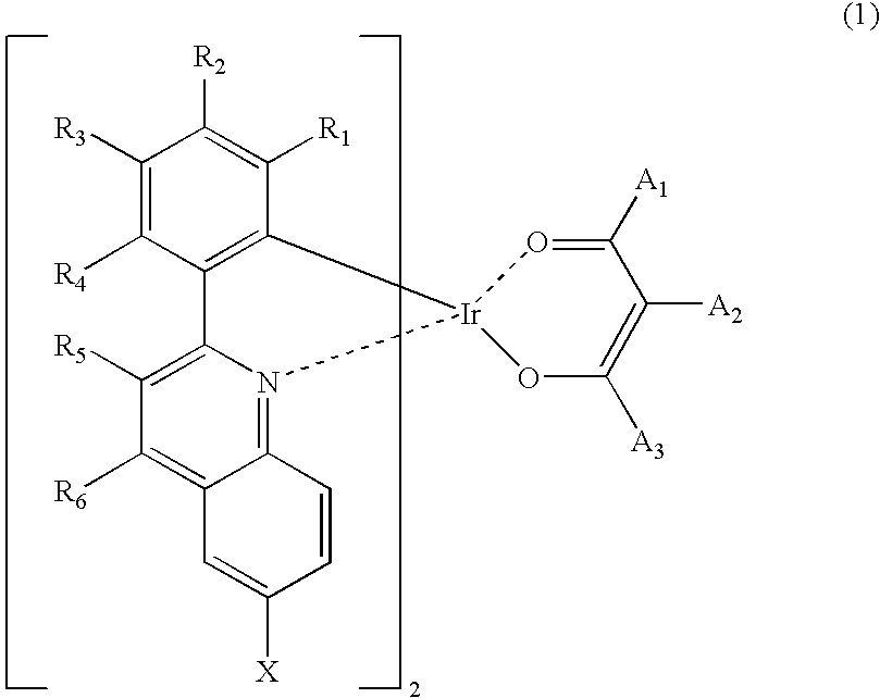
Synthesis of iridium (III) (2-(3,5-dimethylphenyl)-6-trimethylsilylquinolinato-N,C2′)2(2,4-pentanedionate-O,O)
[0034]15.0 g (0.05 mole) of 2-(3,4-dimethylphenyl)-6-trimethylsilylquinoline, 7.0 g (0.02 mole) of iridium (III) chloride hydrate (Ir(III)Cl3.3H2O), 140 ml of 2-ethoxyethanol and 70 ml of distilled water (H2O) were refluxed in a dry three-neck round-bottom flask for 24 hours and cooled to room temperature. Water was added to the reaction mixture to precipitate a crystal. The crystal was collected by filtration and washed with water to give 10.0 g of a dimeric complex. 10.0 g (0.01 mole) of the dimeric complex, 1.3 g (0.01 mole) of acetylacetone, 2.5 g (0.02 mole) of sodium carbonate (Na2CO3) and 200 ml of 2-ethoxyethanol were stirred in a dry three-neck round-bottom flask at room temperature for 24 hours. Then water was added to the reaction mixture to precipitate a crystal. The crystal was collected by filtration and washed with methanol, affording 3.8 g of the...
example 1-(
2)
Fabrication of Organic Electroluminescent Device
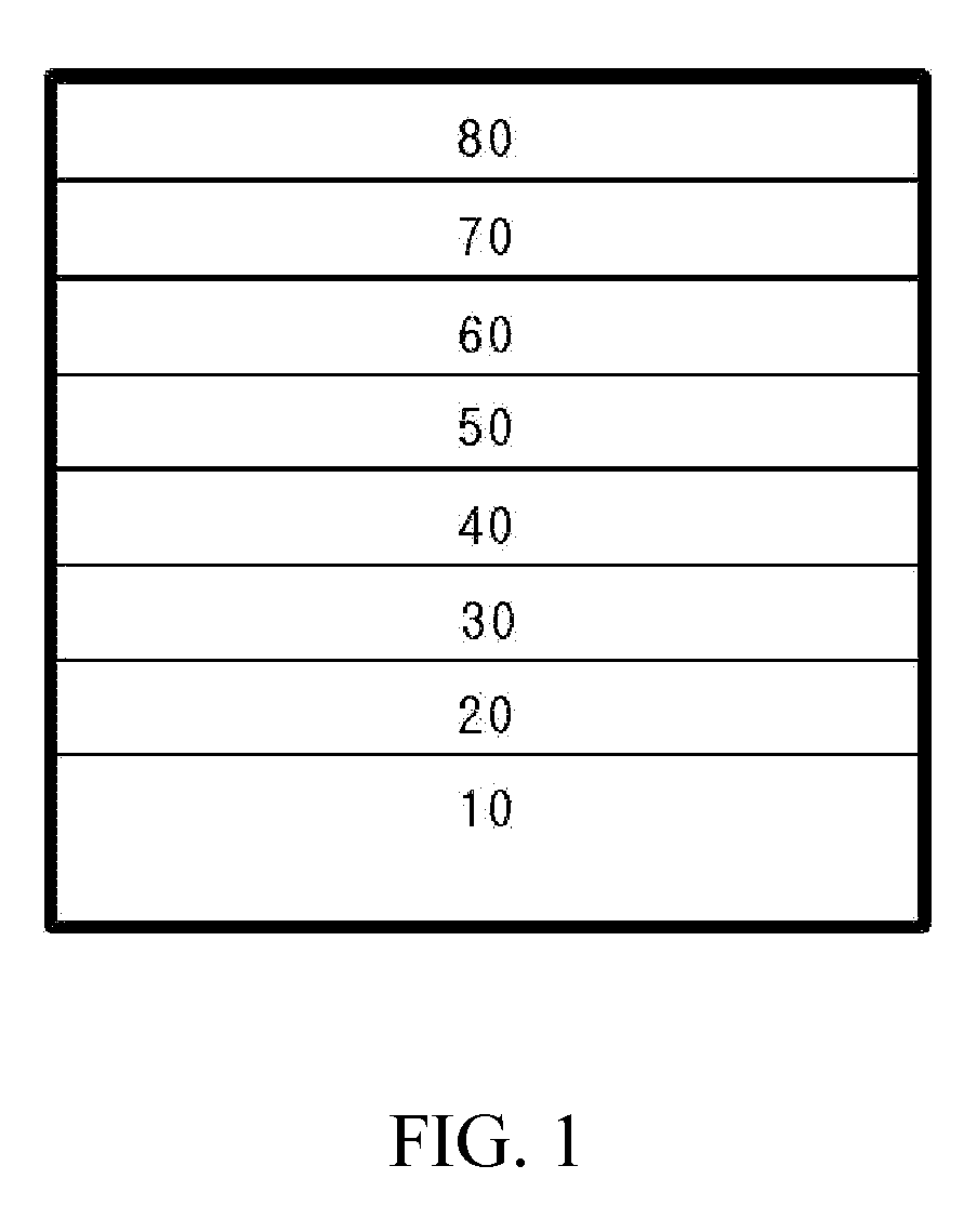
[0036]ITO glass as an anode was patterned to have a light-emitting area of 3 mm×3 mm, followed by cleaning. After the anode was mounted in a vacuum chamber, the pressure of the chamber was adjusted to 1×10⁻⁶ torr. A hole injecting layer (700 Å) composed of HIL-1 (CuPc) (see, the compounds of Formulae 3) and a hole transport layer (300 Å) composed of HTL-2 (α-NPD) (see, the compounds of Formulae 4) were sequentially formed on the anode. Thereafter, a mixture of BAlq and the iridium complex compound (7%) prepared in Example 1-(1) was coated on the hole transport layer to form a 250 Å thick organic light-emitting layer. Then, an electron transport layer (350 Å) composed of ETL-4 (see, the compounds of Formulae 5), an electron injecting layer (5 Å) composed of LiF and an Al cathode (700 Å) were formed in this order on the organic light-emitting layer to fabricate an organic electroluminescent device.
example 2
Example 2-(1)
Synthesis of iridium (III) (2-(3,5-dimethylphenyl)-6-trimethylsilylquinolinato-N,C2′)2(3-methyl-2,4-pentanedionate-O,O)
[0037]27.5 g (0.09 mole) of 2-(3,5-dimethylphenyl)-6-trimethylsilylquinoline, 12.8 g (0.04 mole) of iridium (III) chloride hydrate (Ir(III)Cl3.3H2O), 384 ml of 2-ethoxyethanol and 128 ml of distilled water (H2O) were refluxed in a dry three-neck round-bottom flask for 24 hours and cooled to room temperature. Water was added to the reaction mixture to precipitate a crystal. The crystal was collected by filtration and washed with water to give 30.0 g of a dimeric complex. 15.0 g (0.01 mole) of the dimeric complex, 3.1 g (0.03 mole) of 3-methyl-2,4-pentanedione, 3.8 g (0.04 mole) of sodium carbonate (Na2CO3) and 300 ml of 2-ethoxyethanol were stirred in a dry three-neck round-bottom flask at room temperature for 24 hours. After completion of the reaction, water was added to the reaction mixture to precipitate a crystal. The crystal was collected by filtrat...
PUM
| Property | Measurement | Unit |
|---|---|---|
| Efficiency | aaaaa | aaaaa |
| Transport properties | aaaaa | aaaaa |
| Purity | aaaaa | aaaaa |
Abstract
Description
Claims
Application Information
 - R&D
- Intellectual Property
- Life Sciences
- Materials
- Tech Scout
- Unparalleled Data Quality
- Higher Quality Content
- 60% Fewer Hallucinations
Browse by: Latest US Patents, China's latest patents, Technical Efficacy Thesaurus, Application Domain, Technology Topic, Popular Technical Reports.
© 2025 PatSnap. All rights reserved.Legal|Privacy policy|Modern Slavery Act Transparency Statement|Sitemap|About US| Contact US: help@patsnap.com


