
Optical attenuator

a technology of optical attenuators and attenuators, which is applied in the direction of optical light guides, optical waveguide light guides, instruments, etc., can solve problems such as optical interference, and achieve the effects of suppressing optical signal deterioration, and reducing polarization dependent loss

Inactive Publication Date: 2009-04-23
MATSUSHITA ELECTRIC WORKS LTD
View PDF1 Cites 0 Cited by
  • Summary
  • Abstract
  • Description
  • Claims
  • Application Information

AI Technical Summary

Benefits of technology

[0023]According to the optical attenuator of claim 1, since the first recess and the second recess are formed in the positional relationship of opposite directions with respect to the axial direction of the optic axis of light, the resulting optical waveguide configuration allows the light to be attenuated. Additionally, as the light is attenuated under condition that the refractive-index distributions caused by the first optical attenuating heater and the second optical attenuating heater differs from each other in between the first optical waveguide and the second optical waveguide, it is possible to reduce a polarization dependent loss caused by an asymmetric refractive-index distribution. Thus, without utilizing the interference of lights, it is possible to reduce the polarization dependent loss by a thermo-optic effect, accomplishing a desired optical attenuation.
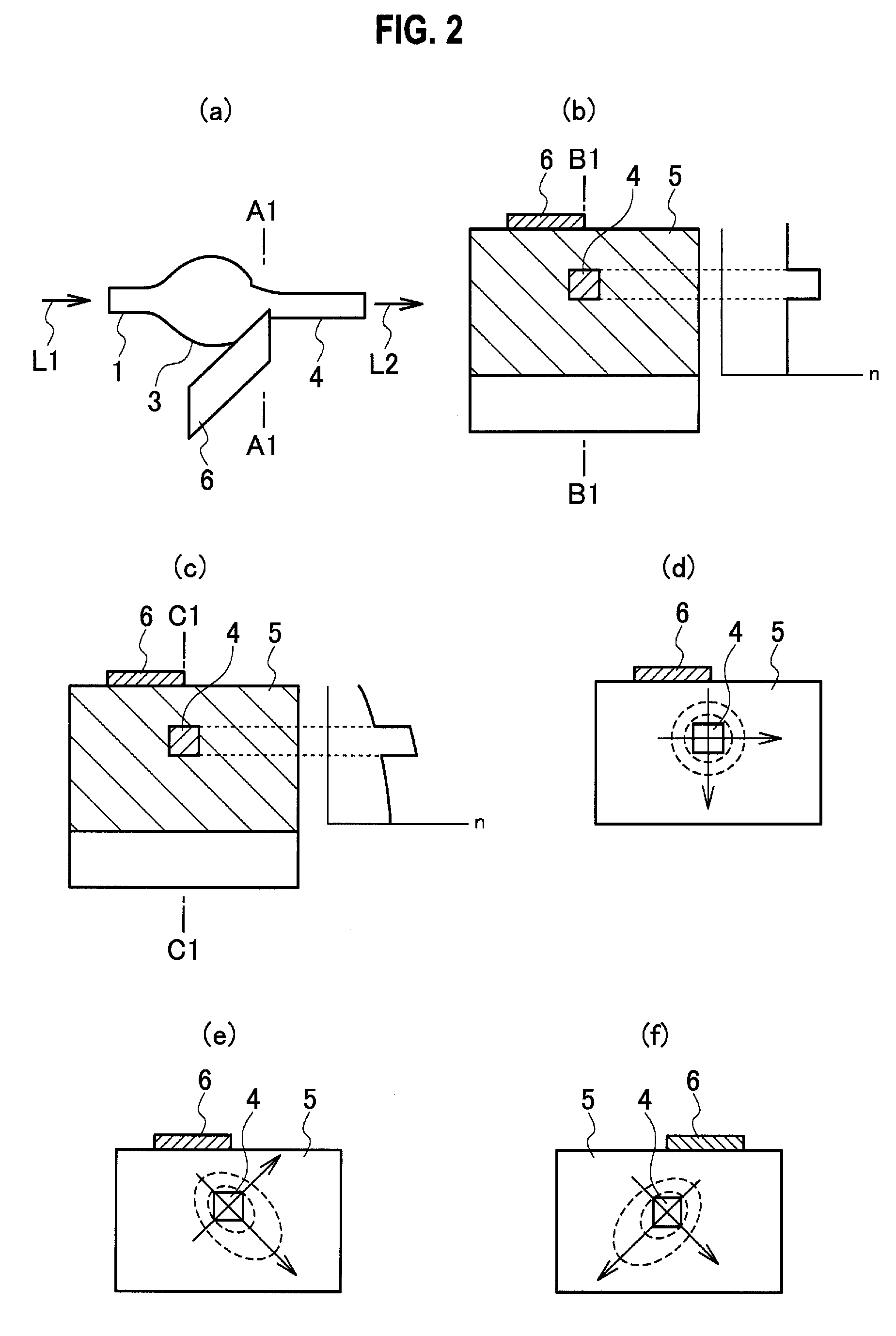
[0024]Further, according to the optical attenuator of claim 2, since the first recess / the first optical attenuating heater and the second recess / the second optical attenuating heater are formed in opposite positional relationships in the axial direction of the optic axis of the light that is inputted through the input optical waveguide, transmitted through the first optical waveguide, the connecting optical waveguide and the second optical waveguide and outputted from the output optical waveguide, it is possible to make an attenuation due to the optical waveguide profile and the refractive index distribution symmetrical in the width direction of an optical waveguide. Thus, when activating both of the first optical attenuating heater and the second optical attenuating heater to generate heat, a direction where the refractive index distribution is deflected by the first optical waveguide and the second optical waveguide is reversed to allow a difference in the polarized state to be averaged between the first optical waveguide and the second optical waveguide.
[0025]Further, according to the optical attenuator of claim 3, since at least either the positional relationship between the optic axis of the light inputted into the first optical waveguide through the input optical waveguide and the optic axis of the light outputted from the first optical waveguide to the connecting optical waveguide, or the positional relationship between the optic axis of the light inputted into the second optical waveguide through the connecting optical waveguide and the optic axis of the light outputted from the second optical waveguide to the output optical waveguide is out of alignment, it is possible to enhance the attenuating effect for light in comparison with a case of no misalignment.
[0026]Further, according to the optical attenuator of claim 4, since the connecting optical waveguide is formed, at its part in the vicinity of the first optical waveguide, with the optical waveguide width which is narrower than the optical waveguide width of the connecting optical waveguide part in the vicinity of the second optical waveguide, it is possible to diffuse light when passing through the narrowed connecting optical waveguide and also possible to diffuse unnecessary light leading to a deterioration of optical signals, suppressing a deterioration of optical signals accompanies with the attenuation of light.
[0027]Further, according to the optical attenuator of claim 5, since the connecting optical waveguide have the narrowed part arranged in the vicinity of the second optical waveguide to have a narrowed optical waveguide width, or the output optical waveguide have the narrowed part arranged in the vicinity of the second optical waveguide to have a narrowed optical waveguide width, the narrowed part can diffuse light, whereby it is possible to suppress a deterioration of optical signals accompanies with the attenuation of light.
[0028]Further, according to the optical attenuator of claim 6, the first recess / the first optical attenuating heater and the second recess / the second optical attenuating heater are formed in opposite positional relationships in the axial direction of the optic axis of the light that is inputted through the input optical waveguide, transmitted through the first optical waveguide, the connecting optical waveguide and the second optical waveguide and outputted from the output optical waveguide. Further, the first recess is arranged on one side of the output optical waveguide, while the second recess is arranged on one side of the input optical waveguide. Therefore, as the first optical attenuating heater and the second optical attenuating heater can be arranged inversely in the width direction of optical waveguide and also arranged completely symmetrically in the traveling direction of light, it is possible to reduce the polarization dependent loss furthermore.

Problems solved by technology

Thereafter, when the lights in two routes are combined into one again, there is produced an optical interference due to this phase change.

Method used


Image

  • Optical attenuator
  • Optical attenuator
  • Optical attenuator

Examples


Embodiment Construction

[0064]Referring to accompanying drawings, embodiments of the present invention will be described below.

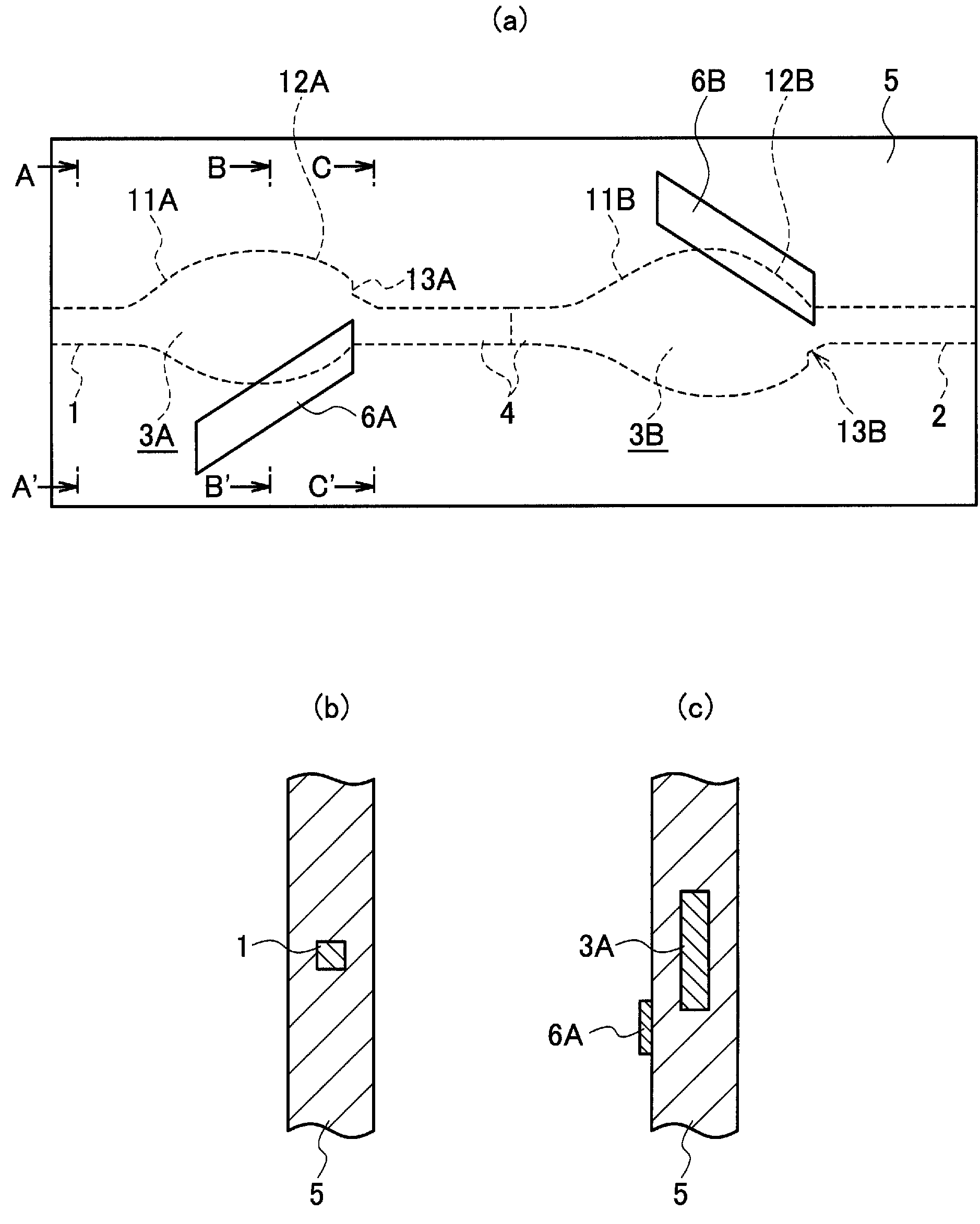
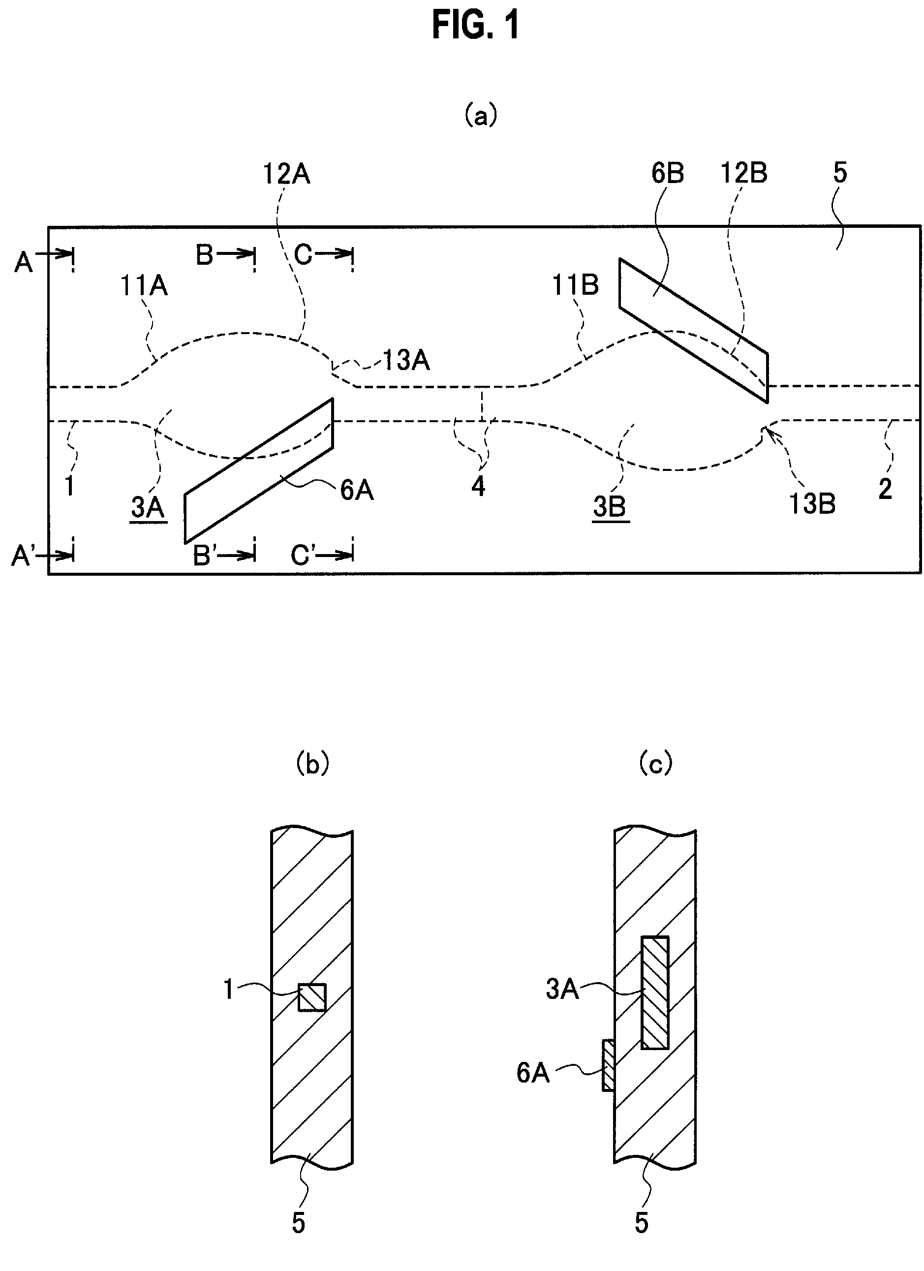
[0065]The present invention is applied on an optical attenuator, for example, whose plan view is shown in FIG. 1(a) and a sectional view of the optical attenuator is shown in FIG. 1(b). This optical attenuator is used to attenuate optical power with respect to each wavelength for regulation in WDM (Wavelength Division Multiplexing) communication in an optical communication field. When a light having a certain wavelength is inputted, the optical attenuator controls attenuation of the light and subsequently outputs it from an output optical waveguide 2. Note that the optical attenuator of FIG. 1 is nothing but a type of optical attenuator that outputs light upon regulating its optical attenuation, providing one channel of optical power.

[0066]This optical attenuator comprises a first optical waveguide 3A on a front stage connected to an input optical waveguide 1, a second optical wave...


PUM

PropertyMeasurementUnit
refractive indexaaaaaaaaaa

Abstract

In an optical attenuator, there are a first optical waveguide 3A connected to an input optical waveguide 1, a second optical waveguide 3B connected to an output optical waveguide 2 and a connecting optical waveguide 4, which are connected with each other in series. A first recess 13A and a second recess 13B are formed in a positional relationship of opposite directions with respect to an axial direction of an optic axis of light that is inputted through the input optical waveguide 1, transmitted through the first optical waveguide 3A, the connecting optical waveguide 4 and the second optical waveguide 3B and outputted from the output optical waveguide 2. Further, a first optical attenuating heater 6A and a second optical attenuating heater 6B are arranged so as to produce opposite refractive index distributions in the axial direction of the optic axis of the light that is inputted through the input optical waveguide 1, transmitted through the first optical waveguide 3A, the connecting optical waveguide 4 and the second optical waveguide 3B and outputted from the output optical waveguide 2, in the first optical waveguide 3A and the second optical waveguide 3B. The optical attenuator capable of reducing a polarization dependent loss for a desired optical attenuation is provided without utilizing an interference of lights.

Description

TECHNICAL FIELD[0001]The present invention relates to an optical attenuator that can regulate optical power of propagated light since an optical waveguide in the attenuator is partially heated to change its refractive index distribution. Particularly, the invention relates to an optical attenuator favorable to WDM (Wavelength Division Multiplexing) communication or the like.BACKGROUND ART[0002]In a wavelength multiplexing communication system, conventionally, a thermo-optic type variable optical attenuator utilizing thermo-optic (TO) effect is known as an optical attenuator for regulating signal intensity with respect to each wavelength on use. This thermo-optic type variable optical attenuator changes refractive index distributions of an optical waveguide core and its circumferential cladding layer while heating a part of optical waveguide by a heater. Consequently, the optical attenuator attenuates intensity of light to be propagated.[0003]As such “optical waveguide” type devices,...

Claims


Application Information

Patent Timeline
Patent Type & Authority Applications(United States)
IPC IPC(8): G02F1/01
CPCG02F1/011G02F1/0147G02F2203/48G02F2203/06G02F2201/16
Inventor UCHIDA, YUICHIMIYAGAWA, NOBUYUKIYAMAJI, TADAHIROMATSUMOTO, TAKUYA
Owner MATSUSHITA ELECTRIC WORKS LTD
Learn More