
Method and an apparatus for timing control of channel estimation

Active Publication Date: 2009-04-23
MEDIATEK INC
View PDF6 Cites 7 Cited by
  • Summary
  • Abstract
  • Description
  • Claims
  • Application Information

AI Technical Summary

Benefits of technology

[0010]Accordingly, the present invention is directed to a method for timing control of channel estimation. The provided method is able to place a CE window at a proper position so as to enable the receiving end to estimate a more complete channel impulse response to enhance the performance of the receiving end.
[0011]The present invention is also directed to an apparatus for timing control of channel estimation for adjusting the position of a CE window to improve the performance of the receiving end.
[0024]Since the present invention uses the number of the delay paths and the channel powers contained by each candidate segment to calculate the metric of each candidate segment, and further decides an optimal segment according to the metric so as to place the CE window at a proper position; therefore, the present invention enables the receiving end to more completely estimate the channel impulse response to improve the performance of the receiving end.

Problems solved by technology

In a wireless communication environment, a Doppler shift caused by movement of a receiving end or a transmitting end or a multipath phenomenon caused by diffraction and refraction of electromagnetic wave traveling through obstacles between the receiving end and the transmitting end makes the received signal at the receiving end interfering by huge interference.
Taking the current code division multiple access system (CDMA system) as an example, although the CDMA system transmits signals of multiple users simultaneously by using different spreading codes respectively corresponding to multiple users and prevents the signals of different users from interfering mutually based on the orthogonality between spreading codes; however, when a transmitted signal in the transmission channel suffers multipath interference, the orthogonality between spreading codes will be destroyed and introduces multiple-user interference (MUI).
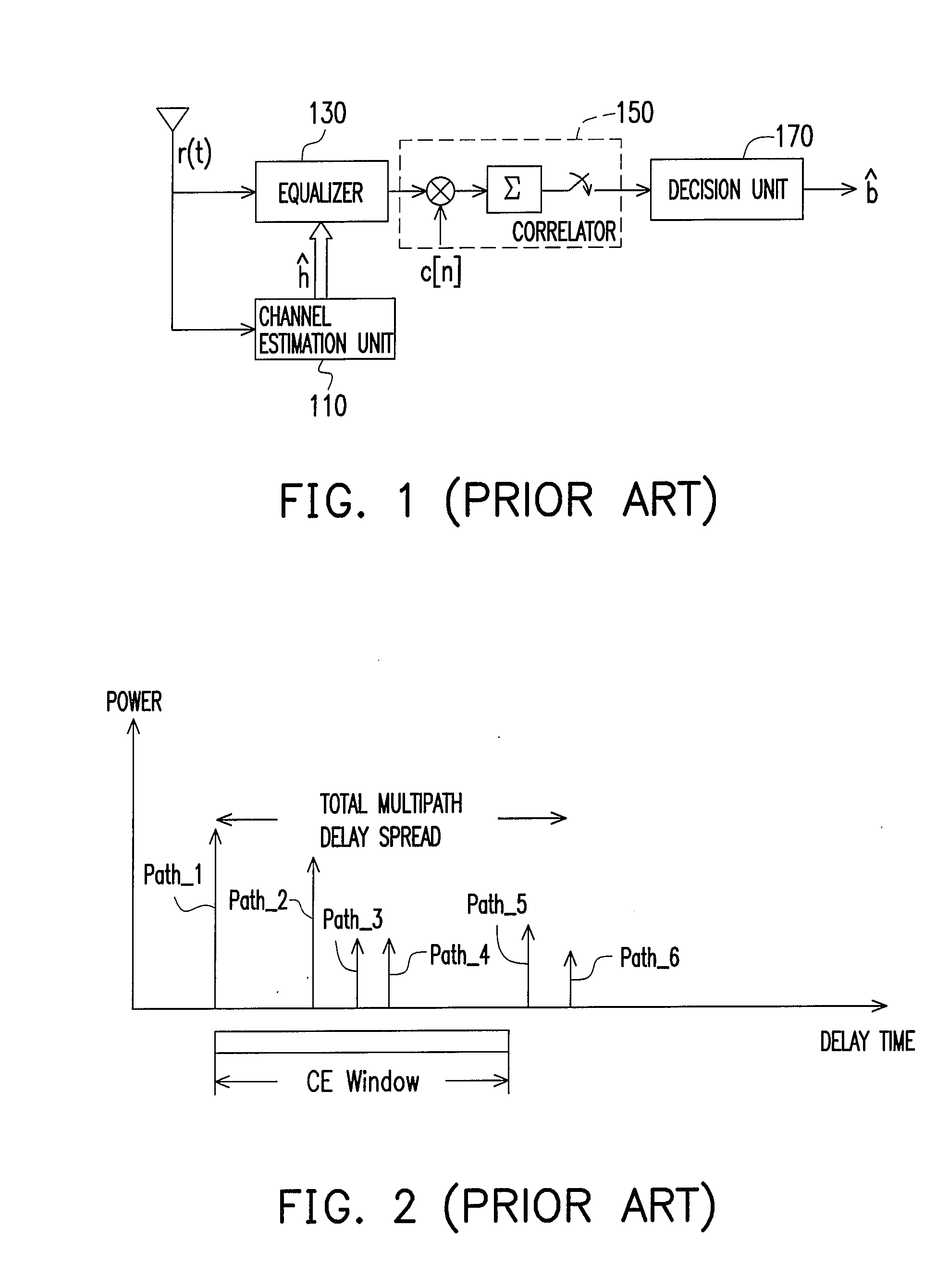
In other words, restricted by the hardware, a CE window is unable to cover all delay paths in a channel, which makes the channel estimation approach fail to estimate the real channel impulse response and further degrades the performance of the equalizer.

Method used


Image

  • Method and an apparatus for timing control of channel estimation
  • Method and an apparatus for timing control of channel estimation
  • Method and an apparatus for timing control of channel estimation

Examples


Embodiment Construction

[0042]In order to place a CE window at a proper position to obtain a satisfied channel estimation result, the present invention provides a method and a timing control apparatus for timing control of channel estimation. For depiction convenience, the embodiments of the present invention are exemplarily based on a CDMA system, but anyone skilled in the art should understand the present invention is applicable to other spreading system or any communication system using a channel estimation approach for adjusting the position of a CE window.

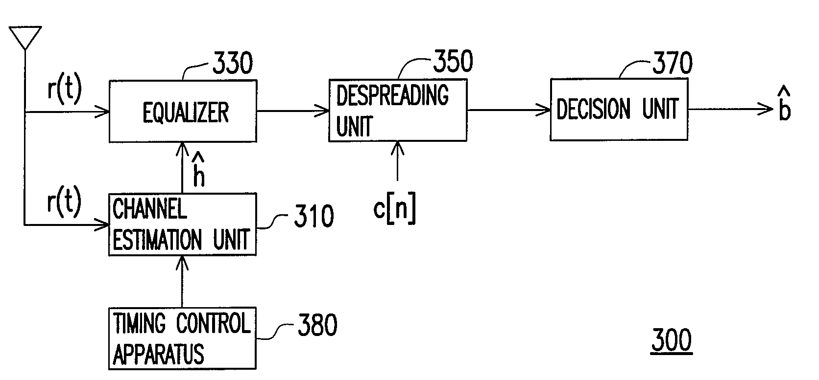
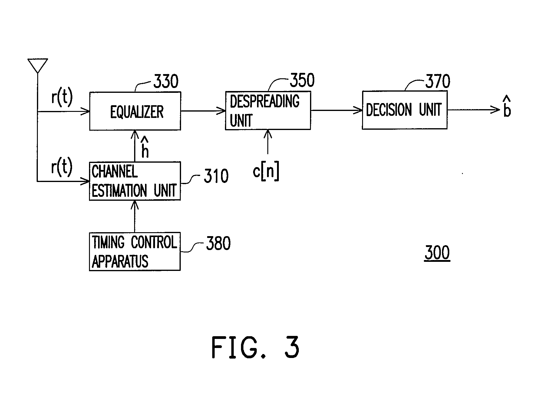
[0043]FIG. 3 is a systematic block diagram of a receiving end according to an embodiment of the present invention. Referring to FIG. 3, a receiving end 300 includes a channel estimation unit 310, an equalizer 330, a decision unit 370 and a timing control apparatus 380. The receiving end 300 receives a received signal r (t) sent from a transmitting end through a wireless transmission channel. The channel estimation unit 310 estimates a channel gain ĥ ...


PUM


Abstract

The present invention relates to a method and an apparatus for timing control of channel estimation. The method includes: sequentially shifting a channel estimation window in a power-delay profile in a specific time interval to obtain a plurality of candidate segments; sequentially calculating a metric corresponding to the candidate segments according to the delay paths and the channel power contained in the candidate segments; among the metrics, finding out an optimal segment with the maximum metric and deciding a timing of channel estimation based on the optimal segment.

Description

CROSS-REFERENCE TO RELATED APPLICATION[0001]This application claims the priority benefit of Taiwan application serial no. 96139462, filed on Oct. 22, 2007. The entirety the above-mentioned patent application is hereby incorporated by reference herein and made a part of specification.BACKGROUND OF THE INVENTION[0002]1. Field of the Invention[0003]The present invention generally relates to a method for timing control, and more particularly, to a method for timing control of channel estimation.[0004]2. Description of Related Art[0005]In a wireless communication environment, a Doppler shift caused by movement of a receiving end or a transmitting end or a multipath phenomenon caused by diffraction and refraction of electromagnetic wave traveling through obstacles between the receiving end and the transmitting end makes the received signal at the receiving end interfering by huge interference. Taking the current code division multiple access system (CDMA system) as an example, although th...

Claims


Application Information

Patent Timeline
IPC IPC(8): H04L27/28
CPCH04L25/0216H04L25/0212
Inventor CHEN, PO-YINGPENG, JEN-WEIKUO, WEI-LY
Owner MEDIATEK INC
Learn More