
Analog power-saving apparatus and method thereof for sharing electric charges

Inactive Publication Date: 2009-04-23
NOVATEK MICROELECTRONICS CORP
View PDF2 Cites 18 Cited by
  • Summary
  • Abstract
  • Description
  • Claims
  • Application Information

AI Technical Summary

Benefits of technology

[0018]Accordingly, the present invention is directed to an analog power-saving apparatus and a method thereof for sharing electric charges, wherein a novel analog judgment mechanism is used to overcome the negative effect caused by the conventional power-saving apparatus for sharing electric charges which uses the judgment mechanism of the digital system of the application device thereof.
[0042]In this way, the analog power-saving apparatus and the method thereof for sharing electric charges provided by the present invention can overcome the negative effect caused by the conventional power-saving apparatus for sharing electric charges which uses the judgment mechanism of the digital system of the application device thereof. Therefore, an application device employs the analog power-saving apparatus and the method thereof for sharing electric charges provided by the present invention can effectively achieve power-saving goal.

Problems solved by technology

However, the above-described mechanism using the digital system of the above-mentioned application device is defective in deciding when the electric charges of the storing / sharing capacitor CEQ need to be shared with the load capacitor CL and deciding when the electric charges in the load capacitor CL to be released need to be stored in the storing / sharing capacitor CEQ.
Further in the durations T2-T4, the output voltage VOUT must fall from the high voltage level to the level of the sharing voltage VEQ first, followed by rising to the high voltage level in the duration T5, but such a course still causes power consumption of the above-mentioned application device.

Method used


Image

  • Analog power-saving apparatus and method thereof for sharing electric charges
  • Analog power-saving apparatus and method thereof for sharing electric charges
  • Analog power-saving apparatus and method thereof for sharing electric charges

Examples


Embodiment Construction

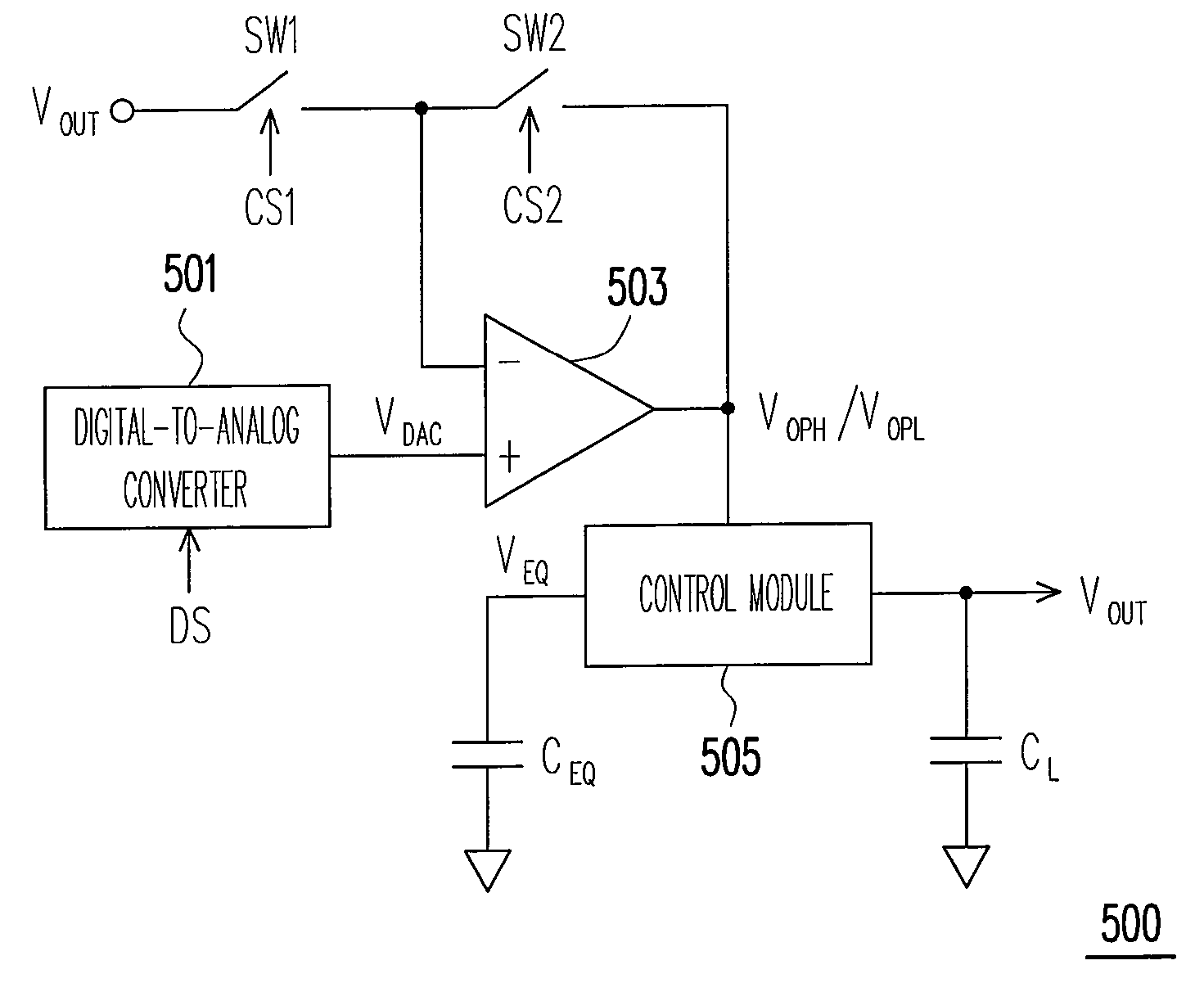
[0053]Reference will now be made in detail to the present preferred embodiments of the invention, examples of which are illustrated in the accompanying drawings. Wherever possible, the same reference numbers are used in the drawings and the description to refer to the same or like parts.

[0054]The technical objective of the present invention is to solve the problem of the negative effect caused by the conventional power-saving apparatus for sharing electric charges which uses the judgment mechanism of the digital system of the application device thereof. In the following, the features and the functions of the present invention are clearly depicted so as to provide anyone skilled in the art for reference.

[0055]FIG. 5 is a block diagram of an analog power-saving apparatus 500 for sharing electric charges according to an embodiment of the present invention. Referring to FIG. 5, the analog power-saving apparatus for sharing electric charges 500 includes a DAC 501, an OPA 503, a first swi...


PUM


Abstract

An analog power-saving apparatus and a method thereof for sharing electric charges enable the application device to entirely achieve power-saving goal by using an analog judgment mechanism. According to the judgment mechanism, in a duration when the energy-storing unit must distribute the stored electric charges to the load capacitor and an amount of the electric charges stored in the energy-storing unit is less than an amount of the electric charges stored in the load capacitor, the path for the energy-storing unit to distribute electric charges to the load capacitor is blocked; and after the load capacitor releases the electric charges thereof to the energy-storing unit for storage, the electric charges stored in the load capacitor after discharge are controlled to be not less than an amount of the electric charges stored in the energy-storing unit after storage.

Description

CROSS-REFERENCE TO RELATED APPLICATION[0001]This application claims the priority benefit of Taiwan application serial no. 96139463, filed on Oct. 22, 2007. The entirety of the above-mentioned patent application is hereby incorporated by reference herein and made a part of this specification.BACKGROUND OF THE INVENTION[0002]1. Field of the Invention[0003]The present invention generally relates to a power-saving apparatus and a method thereof for sharing electric charges, and more particularly, to an analog power-saving apparatus and a method thereof for sharing electric charges.[0004]2. Description of Related Art[0005]In general, an analog circuit employs an operational amplifier (OPA) to drive a load capacitor to provide a required output voltage available for an application circuit. FIG. 1 is a conventional circuit diagram showing an OPA 101 is used to drive a load capacitor CL, wherein the positive input terminal (+) of the OPA 101 is for receiving an analog voltage VDAC generated...

Claims


Application Information

Patent Timeline
IPC IPC(8): H02M3/06H02J7/00
CPCG09G2310/0248G09G2310/0275H03M1/66G09G2330/021H03M1/002G09G2310/0291
Inventor HSIEH, JIN-SHENG
Owner NOVATEK MICROELECTRONICS CORP
Learn More