Induction Hardening Method And Jig Used In Induction Hardening Process
a technology of induction hardening and jig, which is applied in the direction of heat treatment equipment, manufacturing tools, furnaces, etc., can solve the problems of reducing the degree of precision in dimensions, the roundness of a ring-shaped part may be inferior to the roundness before the process is performed, and the satisfactory solution has not yet been found. to prevent the loss of roundness
- Summary
- Abstract
- Description
- Claims
- Application Information
AI Technical Summary
Benefits of technology
Problems solved by technology
Method used
Image
Examples
first embodiment
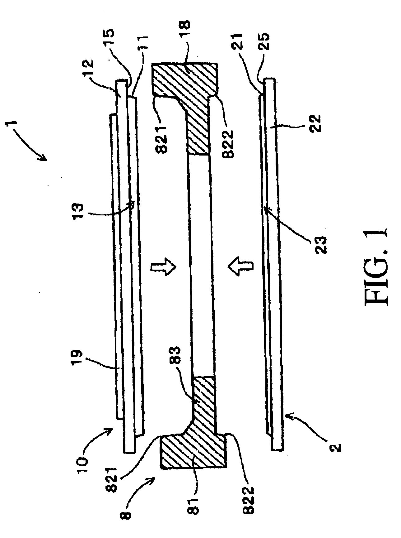
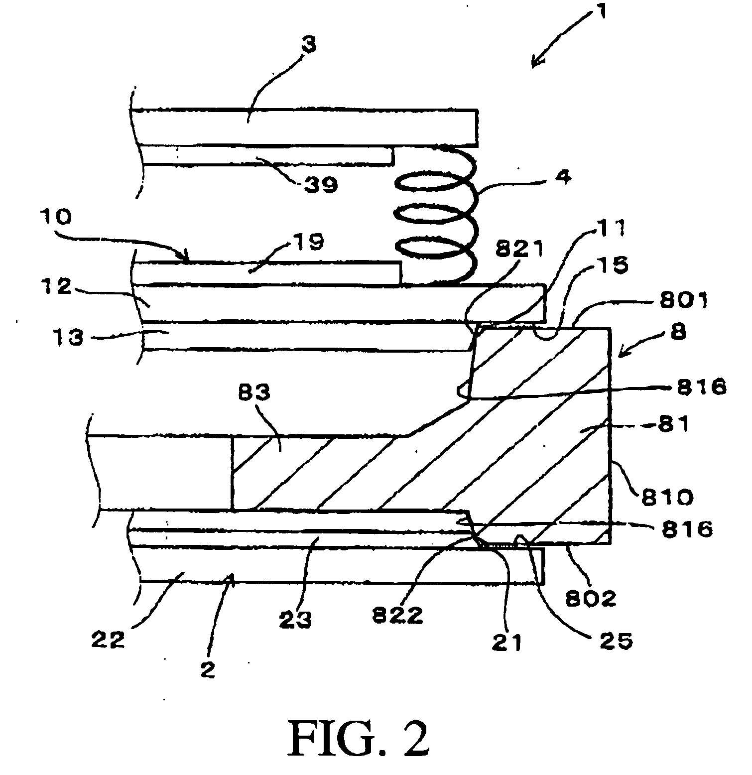
[0049]An induction hardening method and a jig to be used in a hardening process according to an embodiment of the present invention will be explained with reference to FIG. 1 through FIG. 7.
[0050]According to the first embodiment, as shown in FIGS. 7A and 7B, an induction hardening is performed on an outer circumferential surface 810 of an outer ring portion 81 of a steel member 8. The outer ring is substantially in the shape of a circular tube. To be more specific, the steel member 8 is a differential ring gear that is a component of an automatic transmission (A / T) in an automobile. The steel member 8 has, on the outer circumferential surface 810 of the outer ring portion 81, a tooth portion including a large number of teeth 811. On the inner circumference side of the outer ring portion 81 is an inner annular portion 83 that has a smaller axial thickness than the outer ring portion 81. The inner annular portion 83 extends from the axial middle of the inner circumferential surface 8...
second embodiment
[0063]According to a second embodiment of the present invention, as shown in FIGS. 8A to 8D, the first pressing member 10 and the second pressing member 2 (not shown in FIGS. 8A to 8D) are arranged in a setting stage before initiating induction hardening, with the first pressing member 10 having a corner (angle) portion 119 on pressing surface 11 of the first pressing member 10 abutting the inner circumferential surface 816 of the outer ring portion 81, and the second pressing member being configured in the same manner as the first pressing member 10.
[0064]The second embodiment is different from the first embodiment only in terms of the positions at which the pressing surfaces 11 and 21 of the first and the second pressing members 10 and 2 abut against the inner circumferential side of the outer ring portion 81. Thus, according to the second embodiment, it is possible to achieve the same effect as in the first embodiment.
third embodiment
[0065]According to a third embodiment of the present invention, as shown in FIGS. 9A to 9D, the first pressing member 10 and the second pressing member 2 are arranged in a setting stage before an induction hardening processing is performed, the first pressing member 10 being configured so that the pressing surface 11 of the first pressing member 10 abuts against the inner circumferential surface 816 of the outer ring portion 81, and the second pressing member being configured in the same manner as the first pressing member 10.
[0066]Again, the third embodiment is different from the first embodiment only in terms of the positions at which the pressing surfaces 11 and 21 of the first and the second pressing members 10 and 2 abut against the inner circumferential side of the outer ring portion 81. Thus, according to the third embodiment, it is possible to achieve the same effect as in the first embodiment.
Experimental
[0067]In order to quantitatively evaluate the advantageous effect of t...
PUM
| Property | Measurement | Unit |
|---|---|---|
| shape | aaaaa | aaaaa |
| axial force | aaaaa | aaaaa |
| diameter | aaaaa | aaaaa |
Abstract
Description
Claims
Application Information
 - R&D
- Intellectual Property
- Life Sciences
- Materials
- Tech Scout
- Unparalleled Data Quality
- Higher Quality Content
- 60% Fewer Hallucinations
Browse by: Latest US Patents, China's latest patents, Technical Efficacy Thesaurus, Application Domain, Technology Topic, Popular Technical Reports.
© 2025 PatSnap. All rights reserved.Legal|Privacy policy|Modern Slavery Act Transparency Statement|Sitemap|About US| Contact US: help@patsnap.com


