Membrane element sealing material holding member and membrane element

a technology of membrane elements and sealing materials, applied in the direction of membranes, filtration separation, separation processes, etc., can solve the problems of cumbersome connection operation, degrading the commercial quality of products in some cases, aggravating the outer appearance, etc., and achieves convenient insertion of the center tube, easy deformation, and smooth deformation

Active Publication Date: 2009-04-16
NITTO DENKO CORP
View PDF8 Cites 14 Cited by
  • Summary
  • Abstract
  • Description
  • Claims
  • Application Information

AI Technical Summary

Benefits of technology

The present invention relates to a sealing material holding member for a spiral membrane element used in a variety of applications such as desalination and waste water treatment. The sealing material holding member is attached to the end part of the membrane element and holds an annular sealing material that shuts off the gap between the membrane element and the pressure vessel. The invention provides a sealing material holding member that can hold a center tube at the center and facilitate the insertion of the center tube even if the outer diameter dimension of the center tube varies. This ensures a secure and easy connection between membrane elements for use. The technical effect of the invention is to improve the stability and commercial quality of the membrane element.

Problems solved by technology

When clearance is increased in consideration of such a variation, the center tube 6 is liable to become eccentric relative to the sealing material holding member 10, thereby aggravating the outer appearance and degrading the commercial quality of the product in some cases.
Also, when the center tube 6 is made eccentric, the operation of attaching the membrane element may become cumbersome depending on the structure of the pressure vessel 1, thereby raising a problem in that the connection operation may become cumbersome in connecting a plurality of membrane elements for use, or the like problem.

Method used


Image

  • Membrane element sealing material holding member and membrane element
  • Membrane element sealing material holding member and membrane element
  • Membrane element sealing material holding member and membrane element

Examples


Embodiment Construction

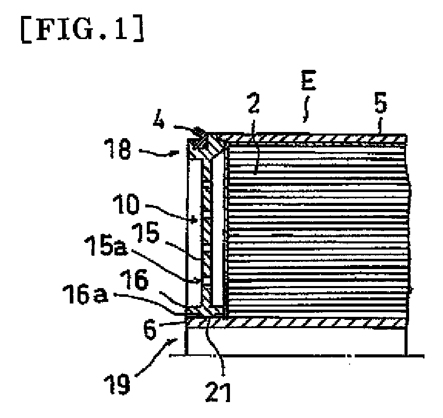
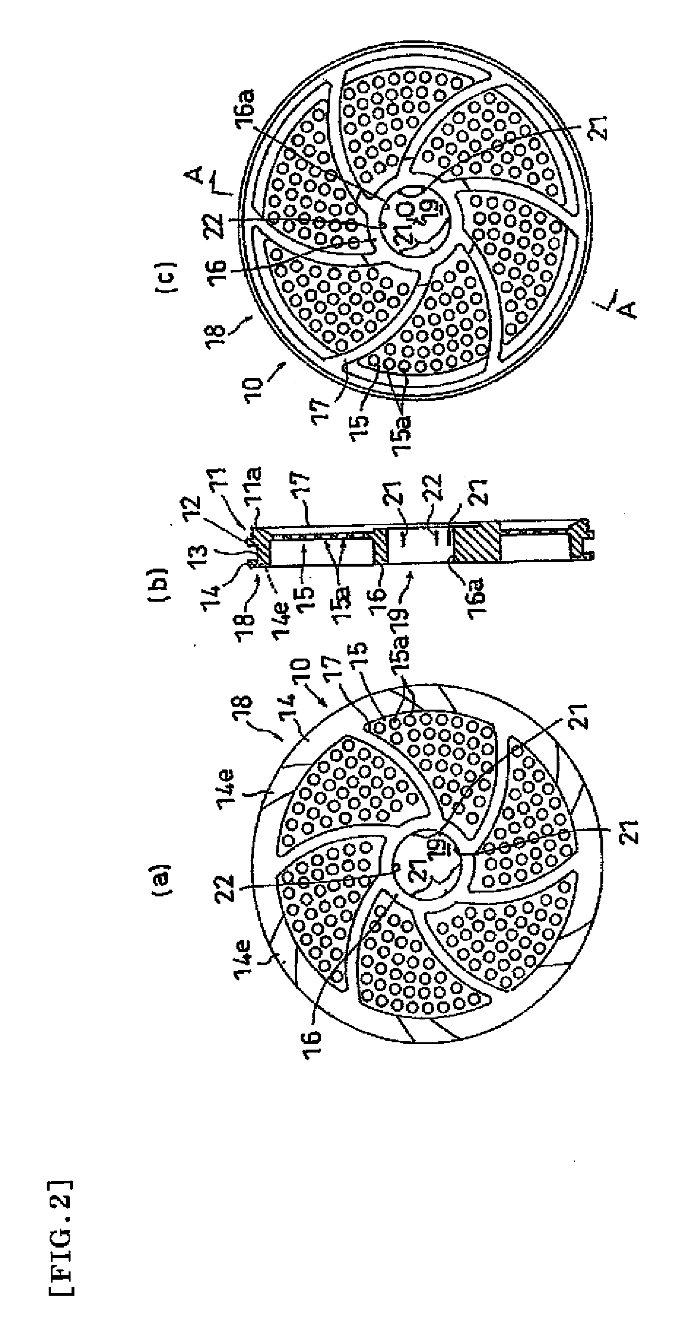
[0036]Hereinafter, embodiments of the present invention will be described with reference to the drawings. FIG. 1 is a half cross-sectional view showing an attachment state of one example of a membrane element sealing material holding member of the present invention. FIG. 2 is a view showing one example of a membrane element sealing material holding member of the present invention, where FIG. 2(a) is a left side view; FIG. 2(b) is a cross-sectional A-A arrow view; and FIG. 2(c) is a right side view. FIGS. 3(a) to 3(d) are enlarged views of an essential part showing a protrusion and an auxiliary protrusion in the membrane element sealing material holding member of the present invention.

[0037]As shown in FIG. 1, the sealing material holding member of the present invention includes a central opening part 19 for insertion of a center tube 6 of a spiral membrane element E, a peripheral opening part 15a for flowing of a raw liquid into a membrane end part of the membrane element E, and an ...


PUM

PropertyMeasurementUnit
lengthaaaaaaaaaa
heightaaaaaaaaaa
outer diameteraaaaaaaaaa

Abstract

A membrane element sealing material holding member that even when the dimension of outer diameter of center tube varies, enables holding of the center tube in the center and further enables easy insertion of the center tube; and a membrane element utilizing the same. The membrane element sealing material holding member comprises central opening (19) for insertion of a center tube of spiral membrane element, peripheral orifice (15a) for flowing of a raw liquid into a membrane end portion of membrane element and outer circumferential part (18) for holding of circular sealing material, wherein the central opening (19) has inner circumferential surface (16a) of cylindrical form with a diameter larger than the outer diameter of the inserted center tube, and wherein at three or more positions on the inner circumferential surface (16a), there is provided projection (21) that has sloping face (21a) on its side of center tube (6) insertion and is deformable at the time of insertion of center tube (6) with an outer diameter larger than that of incircle.

Description

TECHNICAL FIELD[0001]The present invention relates to a sealing material holding member that is attached to an end part of a spiral membrane element for holding a sealing material that shuts off the gap between a pressure vessel and the membrane element, as well as to a membrane element using the same.BACKGROUND ART[0002]Conventionally, a spiral separation membrane module is used for a variety of uses such as desalination of brine or sea water, production of ultrapure water, and processing of waste water. As shown in FIG. 7, a spiral separation membrane module has a structure such that a spiral separation membrane element E is housed in a pressure vessel 1, where the gap between the pressure vessel 1 and the element E is shut off with an annular sealing material 4 so as to let the supplied raw liquid 7 flow efficiently into the element E.[0003]The raw liquid that has flown into the element E is subjected to separation with a separation membrane while flowing to the downstream side a...

Claims


Application Information

Patent Timeline
Patent Type & Authority Applications(United States)
IPC IPC(8): B01D63/00B01D63/10
CPCB01D2313/04B01D63/106Y02A20/131B01D63/107B01D65/003B01D69/1213
Inventor UDA, YASUHIROBEPPU, MASASHIFUJIOKA, HIROKINISHIDA, YUUJICHIKURA, SHINICHIMATSUDA, HIDEKIISHII, KATSUMI
Owner NITTO DENKO CORP
Why Eureka
Try Eureka