Fuel environmental evaluation system

a technology of environmental evaluation and fuel, applied in the field of fuel environmental evaluation system, can solve the problems of hardly identifiable carbon tax payment at each company or place, and the degradation of the environment due to greenhouse effect gases such as carbon dioxide,

Inactive Publication Date: 2009-04-02
HITACHI LTD
View PDF2 Cites 5 Cited by
  • Summary
  • Abstract
  • Description
  • Claims
  • Application Information

AI Technical Summary

Benefits of technology

[0011]The invention enables the environmentally affecting matter emission evaluation including environmentally affecting matter emission quantities generated while the energy itself is distributed and utilities, resulting in detailed evaluation of the amount of the environmentally affecting matter emission. Especially, the invention can provide an effective system that evaluates environmental characteristics of natural energy or energy generated from side products.

Problems solved by technology

Presently, the environmental degradation due to greenhouse effect gases such as carbon dioxide (CO2) becomes an important social problem.
In recent years, the greenhouse gases are pointed out as a cause of the temperature rise on a global scale, which is one of the serious international issues.
In this case, if a carbon tax, which is proposed to suppress CO2 emissions, is imposed on the gasoline as a final product supplied at the gas station, the carbon tax payment at each company or place may be hardly identifiable when facilities that refine, transport, or sell the gasoline are different companies or located in different places.

Method used


Image

  • Fuel environmental evaluation system
  • Fuel environmental evaluation system
  • Fuel environmental evaluation system

Examples


first embodiment

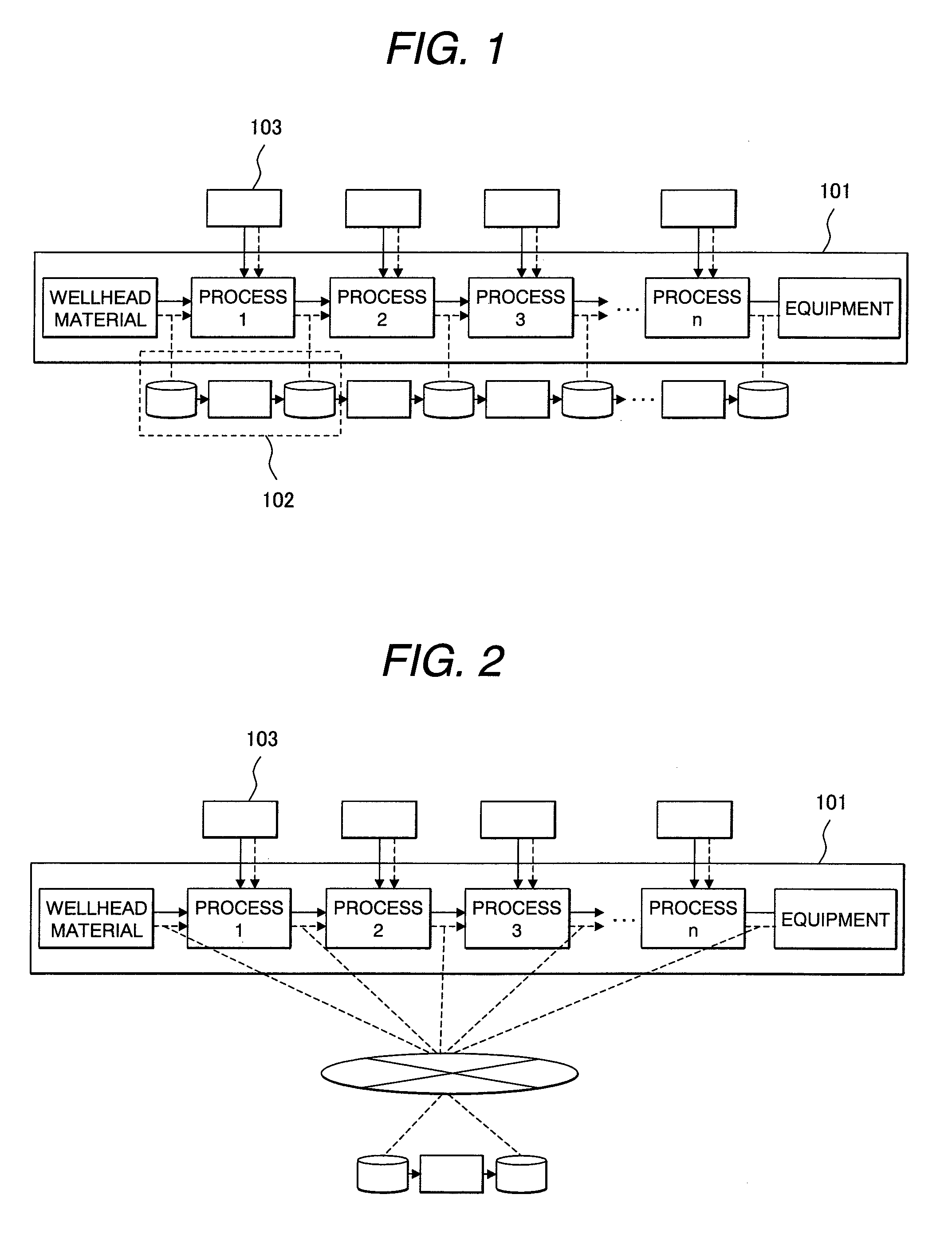
[0028]FIG. 1 is a schematic diagram in accordance with an embodiment of the invention, showing energy distribution processes for distributing a well head material, producing a fuel, and using it. Generally, a well head material is mined and transported to a place for storing, where energy of the material is converted and transformed into fuel. The converted and transformed fuel is transported to another place so as to be supplied to consumers, supplied to and used for the equipment. In FIG. 1, processes for mining, transportation, storage, conversion, transformation, and supply are represented as processes 1, 2, 3, 4, and so on. An environmentally affecting matter emission evaluation system 102 includes following means. One of the means inputs the amount of raw material supplied to the equipment included in each process, the amount of product resulting from the supplied raw material, the type of utility supplied for producing the product, and the amount of utility. Another means sto...

second embodiment

[0039]The following describes an embodiment of an energy production means in the energy environmentally affecting matter emission evaluation system described in the first embodiment.

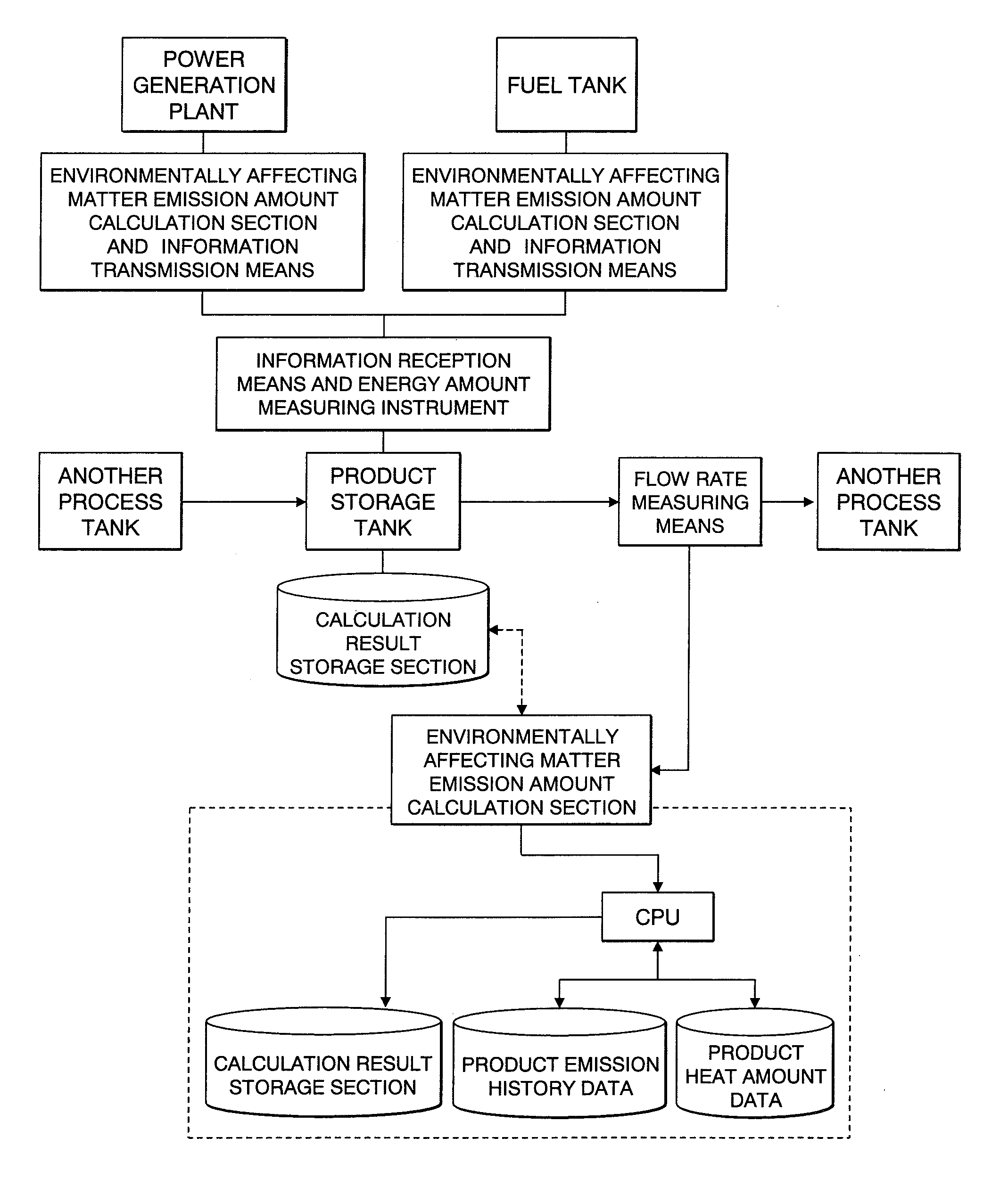
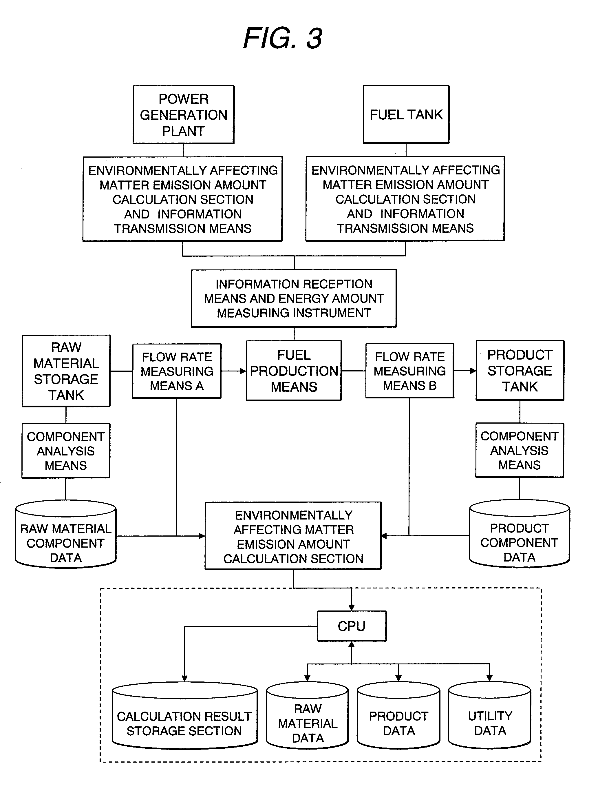
[0040]The energy production means in accordance with the embodiment is constructed as shown in FIG. 3, for example. The energy production means includes following means and tanks. A raw material storage tank stores a raw material. An energy production means receives the raw material from the raw material storage tank through a pipe arrangement, processes the raw material, and produces a product. A product storage tank stores the produced product through a pipe arrangement. A flow rate measuring means measures an amount of raw material supplied to the energy production means and a product amount supplied from the energy production means to the product storage means. The flow rate measuring means is capable of wired or wireless communication with the outside. The energy production means also includes a mea...

third embodiment

[0047]The following describes an embodiment of an energy transportation means in the energy environmentally affecting matter emission evaluation system described in the first embodiment.

[0048]As shown in FIG. 7, the environmentally affecting matter emission evaluation system attached to the energy transportation means is provided for a product transportation tank or a dispenser of the energy transportation means. FIG. 8 shows a configuration of the system, which includes a flow rate measuring means for measuring a product amount when the energy is transferred as a product from a product storage tank of an energy production means to a product transportation tank and for transmitting measurement results via wired or wireless communication to the outside; a means for receiving a product amount from the flow rate measuring means; a means for measuring a utility amount used for the transportation; an environmentally affecting matter emission amount calculation section for calculating an ...


PUM


Abstract

The invention provides a fuel environmental evaluation system for evaluating a fuel environment characteristic in an energy distribution process comprising a means for inputting an amount of raw material supplied to equipment for each process of energy distribution, an amount of product produced from each equipment for each process, and a type and an amount of utility supplied to the equipment for each process when producing the product; a storage means for storing input data; a storage means for storing a basic unit for an amount of environmentally affecting matter emission per unit amount of an environmental emission matter in the raw material, utility and product; an environmental emission calculation section for calculating an amount of environmentally affecting matter emission from data of amounts of the raw material, utility and product, and the basic unit for the amount of environmentally affecting matter emission; and a means for storing a calculation result from the environmental emission calculation section.

Description

CLAIM OF PRIORITY[0001]The present application claims priority from Japanese Patent Application JP 2007-252961 filed on Sep. 28, 2007, the content of which is hereby incorporated by reference into this application.FIELD OF THE INVENTION[0002]The present invention relates to a fuel environmental evaluation system and an environmentally affecting matter emission evaluation system that manages emission of environmentally affecting matters such as carbon dioxide.BACKGROUND OF THE INVENTION[0003]Presently, the environmental degradation due to greenhouse effect gases such as carbon dioxide (CO2) becomes an important social problem. In recent years, the greenhouse gases are pointed out as a cause of the temperature rise on a global scale, which is one of the serious international issues. Under such circumstances, Kyoto Protocol on preventing global warming took effect in February, 2005, to fully implement the international agreements concerning numeric targets for reducing greenhouse effec...

Claims


Application Information

Patent Timeline
Patent Type & Authority Applications(United States)
IPC IPC(8): G06Q99/00G06Q50/00G06Q50/26
CPCG06Q10/30G06Q10/10Y02P90/84Y02W90/00
Inventor NOUJIMA, MASAFUMIKOMURA, AKIYOSHIISHIKAWA, TAKAO
Owner HITACHI LTD
Why Eureka
Try Eureka