Exit stay apparatus with intermediate flange

a technology of exit stay and exit tube, which is applied in the direction of liquid fuel engine, greenhouse gas reduction, renewable energy generation, etc., can solve the problems of significant head loss, significant efficiency loss, and decrease in turbine efficiency, so as to eliminate the loss of turbine efficiency and strong pulsation in the draft tube, and reduce the maximum efficiency

Inactive Publication Date: 2009-04-02
GOKHMAN ALEXANDER
View PDF10 Cites 4 Cited by
  • Summary
  • Abstract
  • Description
  • Claims
  • Application Information

AI Technical Summary

Benefits of technology

[0030]The present invention discloses an exit stay apparatus with intermediate exit flange for a reaction hydraulic turbine with runner blades secured to the runner crown. The purpose of the invention is to eliminate the loss of turbine efficiency and strong pulsations in draft tube caused by th

Problems solved by technology

It ultimately dissipates due to the viscosity of water, causing a significant loss of head in turbine what results in a decrease of turbine efficiency given by:
However, with variation of Ht and especially with variation of Pt, there is a significant loss of efficiency due to the axial circular vortex in reaction hydraulic turbines with runner blades secured to the runner crown and having a draft tube with an elbow.
In order to enable exit stay apparatus to eliminate central vortex at all operating regimes and, therefore, increase efficiency of react

Method used


Image

  • Exit stay apparatus with intermediate flange
  • Exit stay apparatus with intermediate flange
  • Exit stay apparatus with intermediate flange

Examples


Embodiment Construction

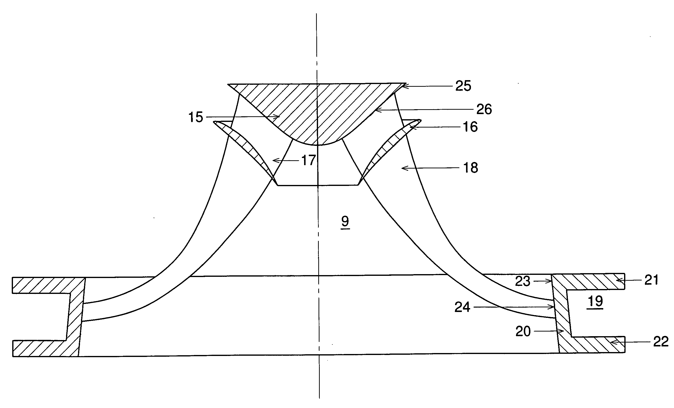
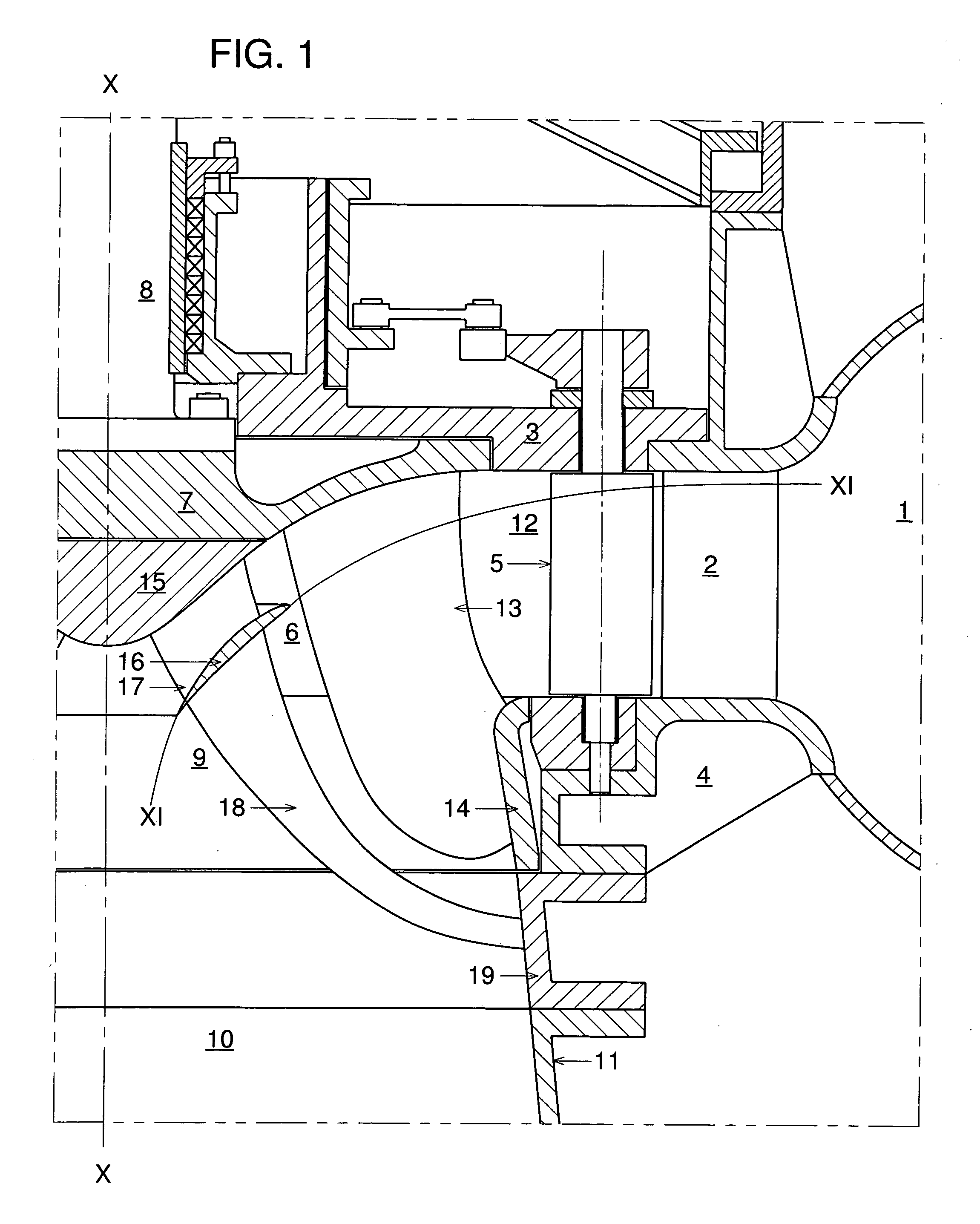
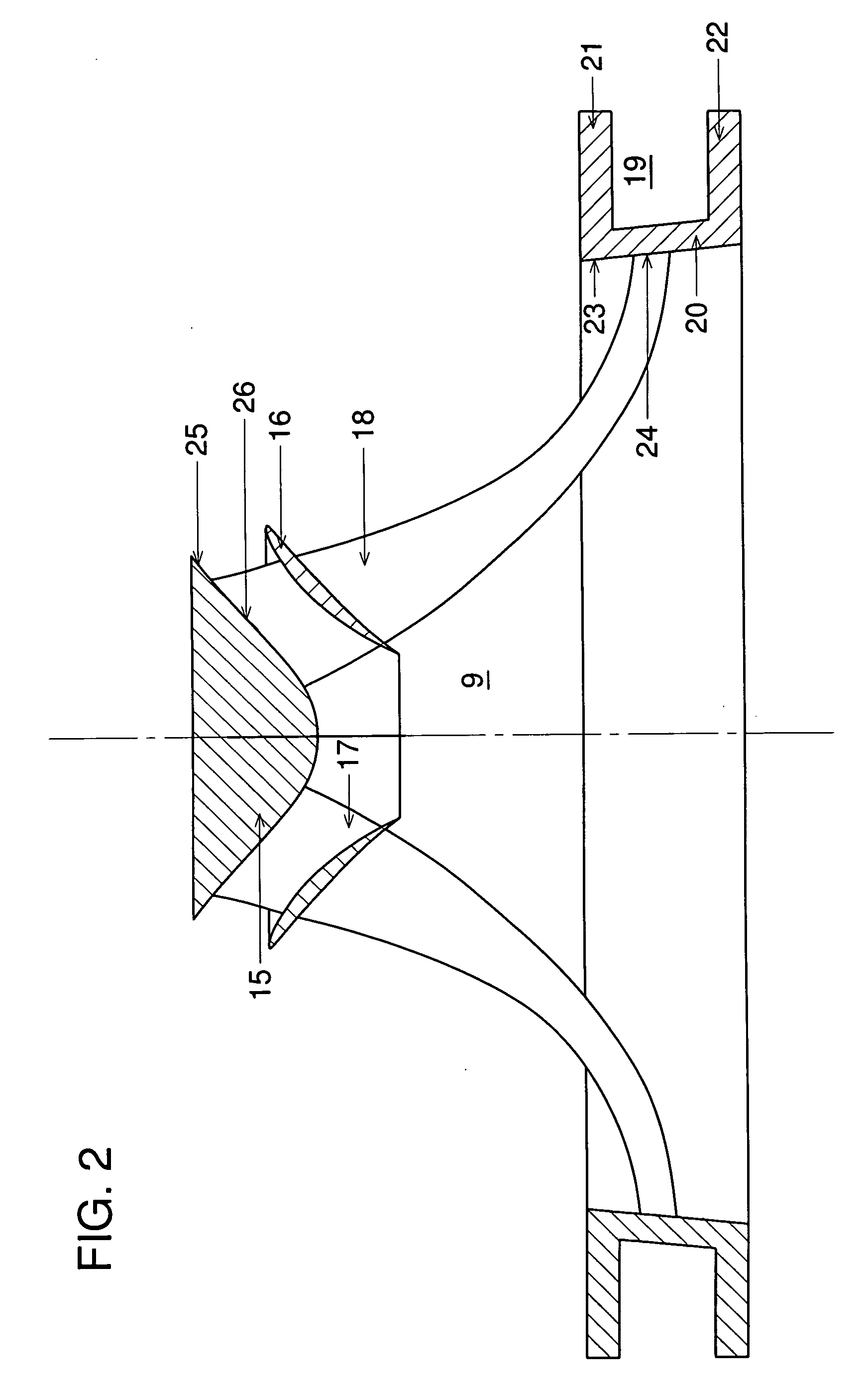
[0040]Referring now to FIG. 1, a radial intake turbine with mixed flow runner a periphery rim and with an exit stay apparatus with intermediate exit flange having an exit stay flange is shown. The installation comprises a spiral casing 1 with radial stay vanes 2, upper head cover 3 and a discharge ring 4 both secured to the spiral casing 1, a guide gate apparatus 12 with radial wicket gates 5 pivotally secured to the head cover 3 and the discharge ring 4, a mixed flow runner 6 with a runner crown 7 secured to the turbine shaft 8, exit stay apparatus 9, and a draft tube 10 with draft tube cone 11, and a draft tube elbow and horizontal diffuser not shown in FIG. 1. Mixed-flow runner 6 together with shaft 8 rotates around the central axis X-X.

[0041]The power output of the turbine is regulated by radial wicket gates 5 which can be pivoted from a maximum open position to a closed position. The mixed flow runner 6 comprises a runner crown 7, turbine blades 13, and rim 14. Turbine blades 1...


PUM


Abstract

The invention is an Exit Stay Apparatus with Intermediate Flange for Francis and propeller hydraulic turbines. The purpose of the invention is to improve the effectiveness of known Exit Stay Apparatus (U.S. Pat. No. 6,918,744, July 2005, for Hydraulic Turbine and Exit Stay Apparatus therefor) in eliminating the axial central vortex and, therefore, in increasing the efficiency and decreasing the flow pressure pulsations in draft tube cone at off optimum operating regimes. The new Exit Stay Apparatus has an intermediate flange between exit stay crown and periphery and two sets of exit stay vanes: crown exit stay vanes secured to the exit stay crown and the intermediate flange and peripheral exit stay vanes secured to the intermediate flange and following to the periphery. When installed in the turbine the peripheral exit stay vanes are secured at the periphery. There are more crown exit stay vanes than the peripheral exit stay vanes and their profiles are longer than the profiles of the peripheral exit stay vanes. The Exit Stay Apparatus with Intermediate Flange is expected to have the same peak efficiency as known Exit Stay Apparatus.

Description

BACKGROUND OF THE INVENTION[0001]This invention relates to reaction hydraulic turbines. More specifically, the invention relates to reaction hydraulic turbines with a radial intake having a spiral casing with inlet stay vanes, a radial guide gate apparatus with wicket gates, either a mixed flow runner or an axial flow runner with runner blades secured to the runner crown, exit stay apparatus and a draft tube with a cone and an elbow.[0002]At any hydroelectric plant the water level in the upper reservoir varies in time. The upper reservoir level depends on the flow of the river on which the plant is situated and on the seasonal demand of the power grid supplied by the plant. Turbine head, denoted by Ht, varies along with the upper reservoir level.[0003]Power output of a turbine, denoted by Pt, is continually adjusted to meet the immediate demand of the power grid. Thus, Pt is also a time dependent variable. Power output of a reaction hydraulic turbine is adjusted by changing the disc...

Claims


Application Information

Patent Timeline
IPC IPC(8): F03B11/04
CPCF03B3/02F03B3/18Y02E10/226Y02E10/223F03B11/04Y02E10/20
Inventor GOKHMAN, ALEXANDER
Owner GOKHMAN ALEXANDER
Why Eureka
Try Eureka