Shaft assembly with lash free bipot joint connection

a technology of lash-free bipot joint and shaft assembly, which is applied in the direction of rod connection, screw, coupling, etc., can solve the problems of increased friction present the prone to wear of the bi-pot joint as described above, and achieves the elimination of lash in the bi-pot joint, high precision, and facilitate the pivotal movement

Inactive Publication Date: 2009-04-02
STEERING SOLUTIONS IP HLDG +1
View PDF21 Cites 2 Cited by
  • Summary
  • Abstract
  • Description
  • Claims
  • Application Information

AI Technical Summary

Benefits of technology

[0007]The pivot block includes a mounting surface disposed against one of the output end and the input end, and further includes a semi-annular surface. The semi-annular surface opposes the mounting surface, and is disposed against the other of the input end and the output end. The semi-annular surface facilitates the pivotal movement of the first shaft relative to the second shaft.
[0008]Accordingly, the subject invention provides a shaft assembly having a bipot joint interconnecting the first shaft and the second shaft, which eliminates the lash in the bipot joint by assembling the bi-pot joint sandwich style. This simplified form of assembly does not require the high precision previously required in other types of universal joints utilized in steering shaft assemblies, thereby reducing the manufacturing costs of the steering shaft assemblies.

Problems solved by technology

Like the cardan style joint, the bipot joint must also be de-lashed, which increases the friction present within the bi-pot joint.
Additionally, the bipot joint as described above are prone to wear.

Method used


Image

  • Shaft assembly with lash free bipot joint connection
  • Shaft assembly with lash free bipot joint connection
  • Shaft assembly with lash free bipot joint connection

Examples


Embodiment Construction

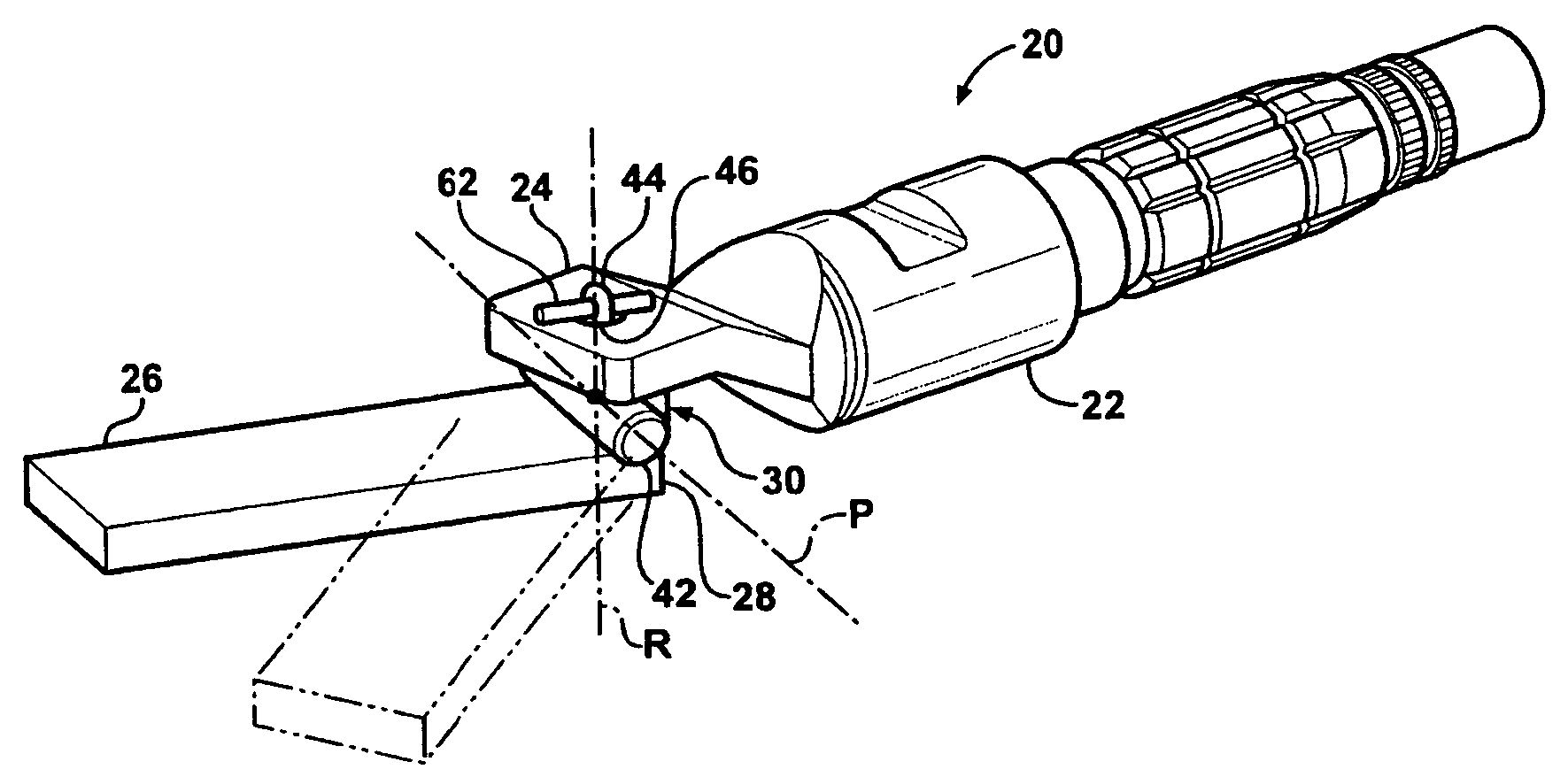
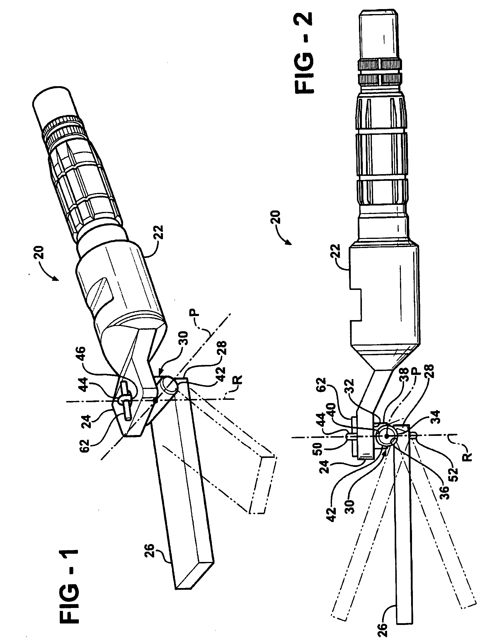
[0016]Referring to the Figures, wherein like numerals indicate corresponding parts throughout the several views, a shaft assembly is generally shown at 20. The shaft assembly 20 shown in the Figures is embodied as a steering shaft system for a vehicle. The steering shaft system is for transmitting rotational inputs form a steering wheel to a steering gear through an indirect path. It should be appreciated, however, that the subject invention may be configured for any number of uses, and is not limited to the steering shaft shown in the Figures.

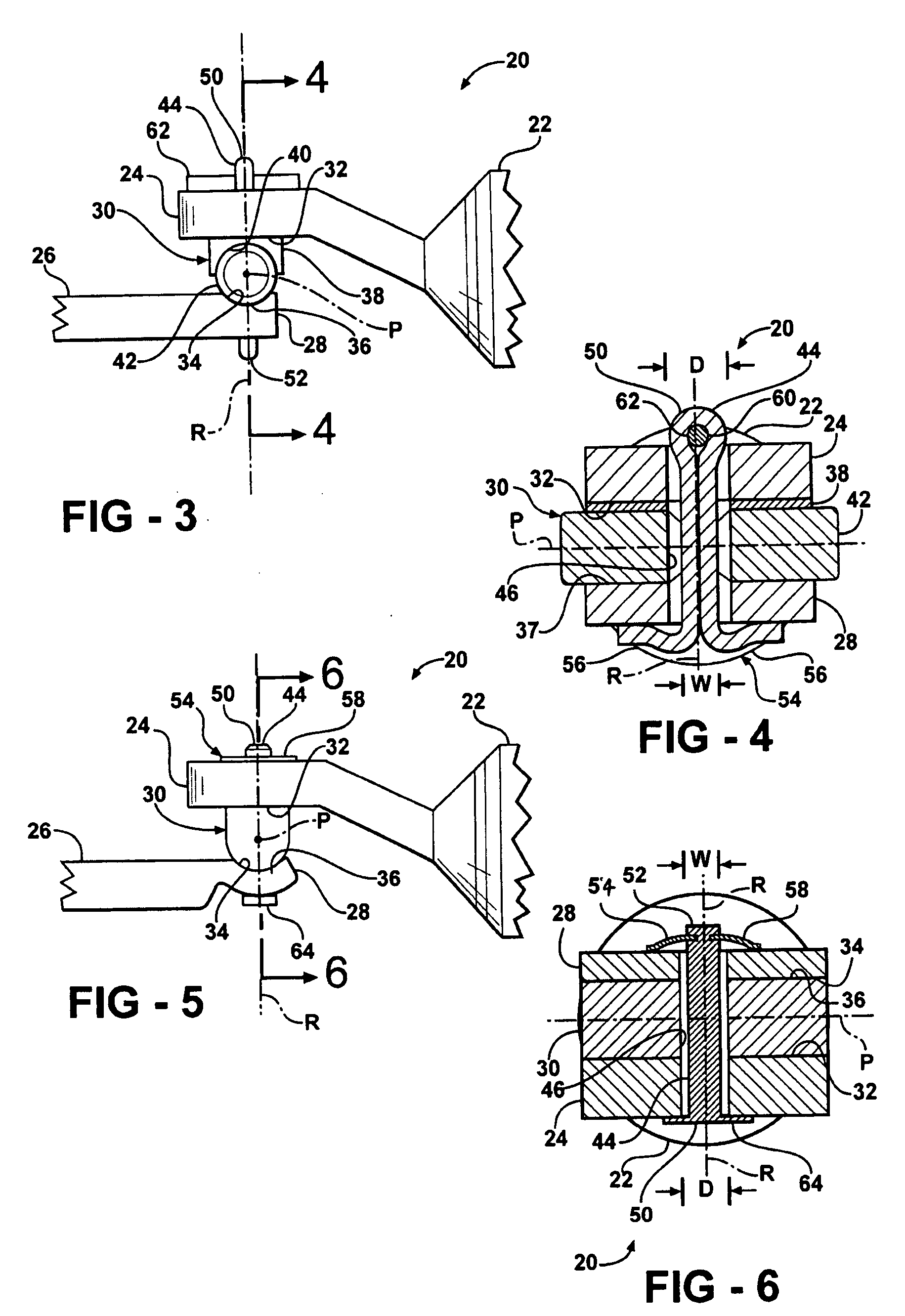
[0017]Referring to FIGS. 1 through 4, the shaft assembly 20 includes a first shaft 22 having an output end 24. The output end 24 includes a rectangular cross section, as best seen in FIGS. 1, 4 and 6. The size of the output end 24 may vary depending on the type of use anticipated for the shaft assembly 20 and the torque transmitted by the shaft assembly 20. It should be appreciated that while the output end 24 of the first shaft 22 includes th...


PUM


Abstract

A shaft assembly having a first shaft and a second shaft interconnected by a bipot joint is disclosed. The first shaft and the second shaft are disposed in overlapping spaced relationship. The bipot joint includes a pivot block sandwiched between the first shaft and the second shaft. The pivot defines a mounting surface abutting one of the first and second shafts, and a semi-annular surface opposing the mounting surface and abutting the other of the first shaft and the second shaft. A fastener extends through a bore defined by the first shaft, the pivot block and the second shaft to interconnect the first shaft, the pivot block and the second shaft. The fastener includes a spring to bias the first shaft, the pivot block and the second shaft together, thereby de-lashing the bipot joint.

Description

BACKGROUND OF THE INVENTION[0001]1. Field of the Invention[0002]The subject invention relates to a shaft assembly, and more specifically to a bipot joint interconnecting a first shaft and a second shaft.[0003]2. Description of the Prior Art[0004]Steering shaft assemblies transmit the movement of a steering wheel through an indirect path to a steering gear. The shaft assemblies typically include at least a first shaft and a second shaft, connected by cardan joint, i.e., a universal joint. Cardan joints permit pivoting movement around a single point in space about two mutually perpendicular axis' that are also mutually perpendicular to a spin axis of the shaft at a 0° joint angle. It is desirable for the shaft assembly to maintain a high torsional stiffness, while keeping frictional loss to a minimum. In order to maintain the high torsional stiffness, the cardan joint must be de-lashed, i.e., remove the slack from the joint. Because most cardan joints utilized in the steering shaft as...

Claims


Application Information

Patent Timeline
Patent Type & Authority Applications(United States)
IPC IPC(8): F16D3/16F16D3/38
CPCF16D3/2052F16D3/24Y10T403/32041Y10T403/32959Y10T403/32622Y10T403/32008
Inventor BODTKER, JOEN C.
Owner STEERING SOLUTIONS IP HLDG
Why Eureka
Try Eureka