
System, tool and method for network monitoring and corresponding network

a network monitoring and tooling technology, applied in the field of network monitoring tools and methods, can solve the problems of large system size, huge processing cost, unreliable system and method, and adversely reduce the sampling size even further to about 2-3% of all traffi

Inactive Publication Date: 2009-04-02
KONINK KPN NV
View PDF32 Cites 103 Cited by
  • Summary
  • Abstract
  • Description
  • Claims
  • Application Information

AI Technical Summary

Benefits of technology

The present invention provides a system and method for monitoring network quality in real-time by analyzing switching events in a network with at least two nodes. The system collects data on switching events from network elements and represents it in a uniform format. By analyzing the data, the system can provide an advanced understanding of network quality as perceived by customers. The system can also adapt its analysis based on the data and provide an alert output file for end-users or a network quality monitoring team. The technical effects of the invention include early warning on malfunctions, improved network management, and improved customer experience.

Problems solved by technology

Moreover as all messages are captured and call-by-call, customer-by customer information is gathered, the system is vast and expensive and requires a huge processing capacity
Disadvantageously, for relatively small networks such as networks for mobile telephony (with a relatively small number of subscriber exchanges), the system and method of EP 541145 will yield unreliable results.
Furthermore, at an increased processor load of an exchange, the DRPC handling tasks of the exchange are reduced in favour of telephony switching tasks, which adversely reduces the sampling size even further to about 2-3% of all traffic.
Moreover, as the information is based on CDR's, the information on the network quality is not real-time.
Such action will result in the collection of vast amounts of data.
Due to the size, the collected data can not be processed in real-time, and consequently the information from such data will be revealed to operations and service personnel only after a certain period of time.
For the purpose of monitoring a network to detect malfunctions in real-time, such a tool from the prior art is not very useful.
Moreover, the vast amount of collected data also requires large investments regarding adequately large storage capacities and computational processing power.
It is noted that the content of most of the collected data is not very useful, since the network will be functioning under normal operation conditions during most of the time.
Furthermore, since no real-time information on network quality is available, responding within a short time to cancel out possible malfunctions (or even to act proactively) is not possible, which may affect customer satisfaction: ultimately, customers may stop using the network and switch to a competitor's network.
Also, commercially available tools will only monitor network elements of the same supplier, which means that in most networks, which are multi-vendor-based, a plurality of such monitoring tools will be needed.
Disadvantageously, in a multi-vendor-based network the cost of having, maintaining, using all necessary tools, and keeping them up-to-date is high.
Moreover, the training of operations and service personnel for each tool is costly also.

Method used


Image

  • System, tool and method for network monitoring and corresponding network
  • System, tool and method for network monitoring and corresponding network
  • System, tool and method for network monitoring and corresponding network

Examples


Embodiment Construction

[0040]For the purpose of teaching of the invention, preferred embodiments of the method and devices of the invention are described in the sequel. It will be apparent to the person skilled in the art that other alternative and equivalent embodiments of the invention can be conceived and reduced to practice without departing form the true spirit of the invention, the scope of the invention being limited only by the appended claims as finally granted.

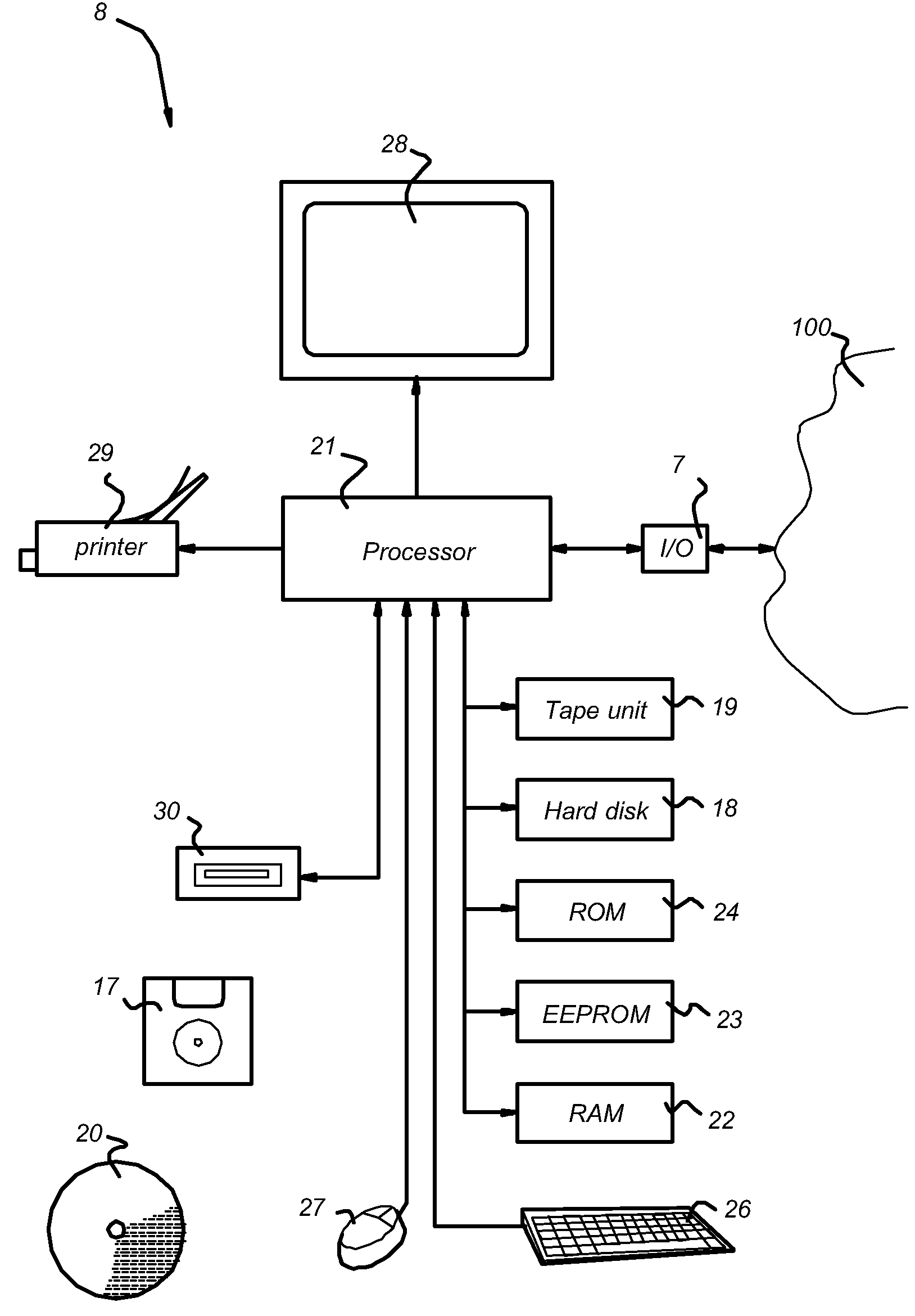
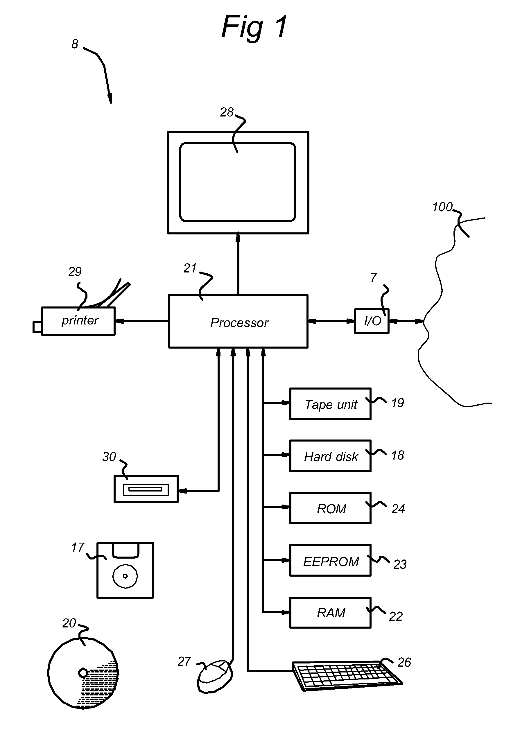
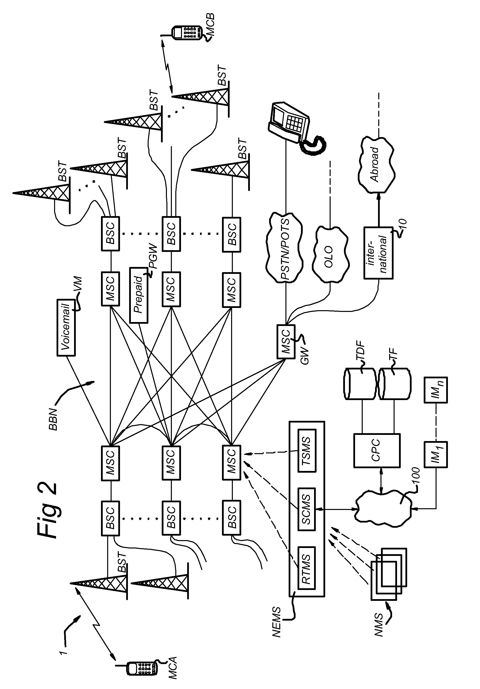
[0041]FIG. 1 shows schematically a telecommunication network in which the system and method for monitoring networks according to the present invention is implemented. The telecommunication network shown as example in FIG. 1 relates to a telecommunication network for mobile telephony such as GSM. It is noted that the system and method for monitoring networks according to the present invention may also be used in a telecommunication network for wired telephony. The telecommunication network 1 comprises a plurality of network elements: e.g., ...


PUM


Abstract

A system, method and tool for monitoring switching events in a network with at least two nodes, and a corresponding network, the system, method and tool including means for representing the events originated from different nodes as data in a uniform format, and means for counting the occurrence of events in a node of the network wherein switching events being represented as the same data are counted as the same event.

Description

PRIORITY FROM U.S. AND FOREIGN PATENT APPLICATIONS[0001]This application claims priority from and is a continuation of U.S. application Ser. No. 10 / 441,558, which was filed on May 20, 2003. U.S. application Ser. No. 10 / 441,558 claims priority to European Patent Office Application No. 02079061.4, filed on Sep. 27, 2002, and European Patent Office Application No. 02076989.9, filed May 21, 2002. U.S. application Ser. No. 10 / 441,558, European Patent Office Application No. 02079061.4, and European Patent Office Application No. 02076989.9 are herein incorporated by reference in their entirety.FIELD OF THE INVENTION[0002]The present invention relates to the field of tools and methods for monitoring the quality of telecommunication networks as perceived by the subscribers of the network. More in particular a tool and a method for monitoring a network being based on the occurrence of switching events in nodes of the network are disclosed.BACKGROUND OF THE INVENTION[0003]Monitoring tools, met...

Claims


Application Information

Patent Timeline
Patent Type & Authority Applications(United States)
IPC IPC(8): H04W24/08H04M3/22
CPCH04M3/2254H04W24/08H04M2201/12
Inventor VAN DER BURG, JOHANNES CORNELISSCHEERS, HARRY WILHELMUS
Owner KONINK KPN NV
Learn More