Vehicle leaf spring suspension with radius arms

a technology of vehicle leaf spring and radius arms, which is applied in the direction of spring/damper, mechanical equipment, transportation and packaging, etc., can solve the problems of high axle vertical movement, many adverse performance and attitude effects on the associated vehicle, and the difficulty of propeller drive shaft angle change, and requires a specially designed and heavier front frame brack

Inactive Publication Date: 2009-04-02
GUTHRIE BRIAN SCOTT
View PDF19 Cites 20 Cited by
  • Summary
  • Abstract
  • Description
  • Claims
  • Application Information

AI Technical Summary

Benefits of technology

[0032]It is an object of the present invention to provide a vehicle leaf spring suspension which overcomes, o

Problems solved by technology

Because this front leaf spring cantilever is very stiff, the instantaneous centre of the axle 33 is very close to the front eye 36 of the leaf spring 32, thereby creating very high axle vertical movements under braking and traction forces which, in turn, produce many adverse performance and attitude effects on the associated vehicle and difficulties associated with propeller drive shaft angle changes.
As discussed above, the main problem created by this type of suspension 41 is that it requires a specially designed and heavier front frame bracket 47.
This arrangement also requires a special frame assembly which increases greatly the expense and production disruption c

Method used


Image

  • Vehicle leaf spring suspension with radius arms
  • Vehicle leaf spring suspension with radius arms
  • Vehicle leaf spring suspension with radius arms

Examples


first embodiment

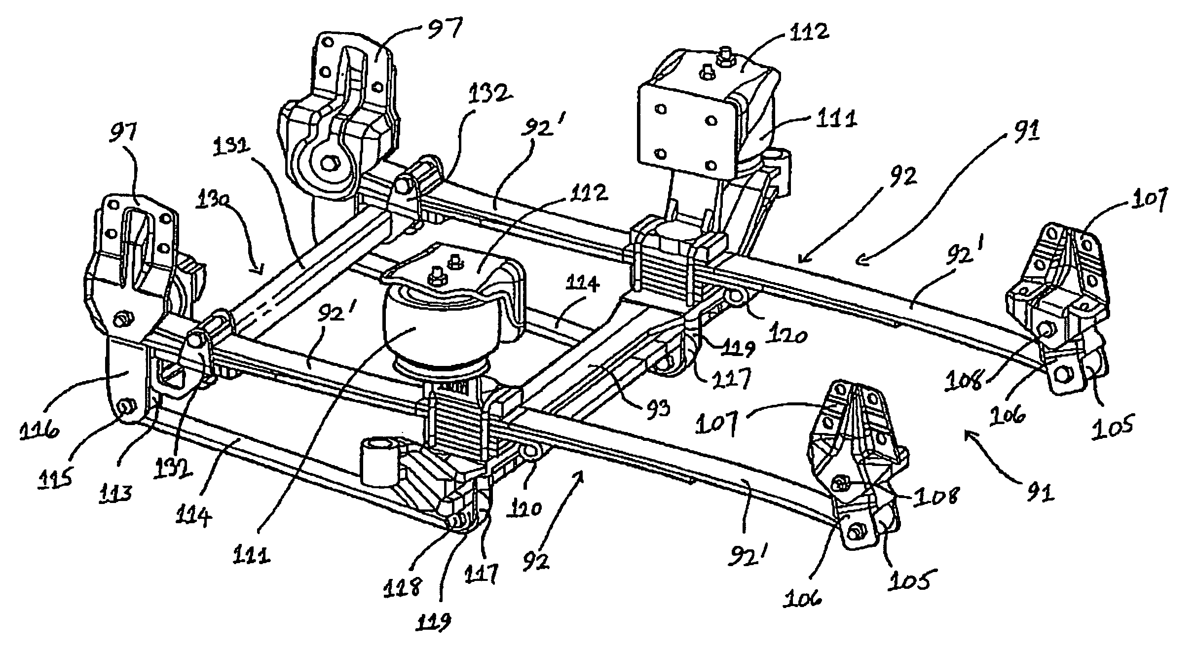
[0113]Referring now to FIGS. 9 and 10 of the accompanying drawings, here is shown vehicle suspension 91 in accordance with the invention, which comprises a pair of double leaf springs 92.

[0114]The front eye 96 of the front cantilever of each upper leaf spring 92′ is connected to the associated vehicle frame (not shown) via a bush 95 mounted with respect to a front hanger bracket 97.

[0115]The rear eye 105 of the rear cantilever of each upper leaf spring 92′ is connected to the vehicle frame by means of a shackle 106 mounted pivotally at 108 to a rear hanger bracket 107.

[0116]Mounted intermediate each pair of front and rear hanger brackets 97, 107, each double leaf spring 92 is clamped rigidly to the transverse axle 93 of the associated vehicle. In turn, further suspension means in the form of an air spring 111 is mounted to each double leaf spring 92 above and adjacent the corresponding end of the axle 93, with the upper end of each air spring 111 being connected rigidly to a frame b...

second embodiment

[0126]suspension 201 shown in FIG. 11 comprises a leaf spring 202 whose front eye 205 is connected to the associated vehicle frame 204 via a bush 203 and frame bracket 206.

[0127]Mounted to the rear end of the leaf spring 202 is further suspension means in the form of an air spring 207, with an axle 208 and associated running wheel 209 provided.

[0128]As in the case of the prior art suspensions of FIGS. 4 to 6, the transverse location of the axle 208 can be provided by any suitable means. In the embodiment shown in FIG. 11, such means is shown diagrammatically at 221 as a transverse location or Panhard rod fastened to an axle bracket 222 which is mounted rigidly to the axle 208. The other end of the rod 221 is connected pivotally to a frame bracket (not shown).

[0129]In accordance with the invention, a radius leaf spring arm 214 has a front eye 217 pivotally connected to the lower end of an extension bracket 216 via a bush 215. The upper end of the bracket 216 is connected rigidly to t...


PUM


Abstract

A vehicle suspension comprising a pair of leaf springs arranged to extend longitudinally of the frame of a vehicle on opposed sides thereof with each leaf spring having one of its ends pivotally connected to the vehicle frame at a fixed location and which have an axle secured thereto between the ends thereof. A first bracket rigidly attaches each leaf spring at or adjacent the fixed location where the end of the leaf spring is connected to the vehicle frame. A radius arm extends longitudinally on each side of the vehicle frame and has one end thereof pivotally connected to the first bracket in a spaced-apart relationship to the fixed location. A second bracket is rigidly attached to the axle and is connected to the other end of the corresponding radius arm in a spaced relationship to the axle. Modified versions of the suspension are also disclosed.

Description

CROSS-REFERENCE TO RELATED APPLICATION[0001]This application claims priority from PCT application Serial No. PCT / US2005 / 016269 filed May 10, 2005, and published as International Publication No. WO 2006 / 121438 on Nov. 16, 2006.FIELD OF THE INVENTION[0002]This invention relates to a vehicle leaf spring suspension with radius arms.BACKGROUND OF THE INVENTION[0003]In vehicle suspensions where the axles are mostly located and controlled by leaf springs, many compromises have to be made. Such compromises can adversely reflect on the suspension performance under various loading conditions to which it is subjected during the operation of the vehicle.[0004]When a vehicle axle is loaded and located with “symmetrical” and “conventional” leaf springs, the axle will deflect, on the suspension, without any change in angle, if any effect from the rear location is ignored.[0005]Throughout this specification, the terms “symmetrical” and “conventional” are as used generally in the suspension industry...

Claims


Application Information

Patent Timeline
IPC IPC(8): B60G11/04
CPCB60G9/003B60G11/04B60G11/465B60G2204/121B60G2202/112B60G2202/152B60G2200/31
Inventor GUTHRIE, BRIAN SCOTT
Owner GUTHRIE BRIAN SCOTT
Why Eureka
Try Eureka