Method for forming raised elements disruptive of the boundary layer

a raised element and boundary layer technology, applied in the field of turbines, can solve the problems of undesirable roughness of raised elements, achieve the effects of improving the behavior of the boundary layer, high fluid velocity, and improving mechanical and thermal properties of parts

Active Publication Date: 2009-04-02
SN DETUDE & DE CONSTR DE MOTEURS DAVIATION S N E C M A
View PDF39 Cites 12 Cited by
  • Summary
  • Abstract
  • Description
  • Claims
  • Application Information

AI Technical Summary

Benefits of technology

[0009]Thanks to this method, the fault of the laser shock technique is turned into an advantage. The raised elements in terms of roughness are considered to be undesirable in the technique of compressing a part by laser shocks because it involves conserving a surface state as little disrupted as possible, the objective being the improvement of the mechanical and thermal properties of the part. The raised elements now see their formation promoted in the method of the invention in order to form disruptions of the boundary layer aimed at modifying the behavior thereof: retarding or initiating turbulence depending on the effect sought. The organization of these disruptions may specifically, depending on the rates / pressure and Reynolds numbers, improve the behavior of the boundary layer by preventing it, for example, from separating for very high fluid velocities.
[0010]It should be noted that the method of the invention continues to take advantage of the laser shock technique to improve the mechanical and thermal properties of the part.

Problems solved by technology

The raised elements in terms of roughness are considered to be undesirable in the technique of compressing a part by laser shocks because it involves conserving a surface state as little disrupted as possible, the objective being the improvement of the mechanical and thermal properties of the part.

Method used


Image

  • Method for forming raised elements disruptive of the boundary layer
  • Method for forming raised elements disruptive of the boundary layer
  • Method for forming raised elements disruptive of the boundary layer

Examples


Embodiment Construction

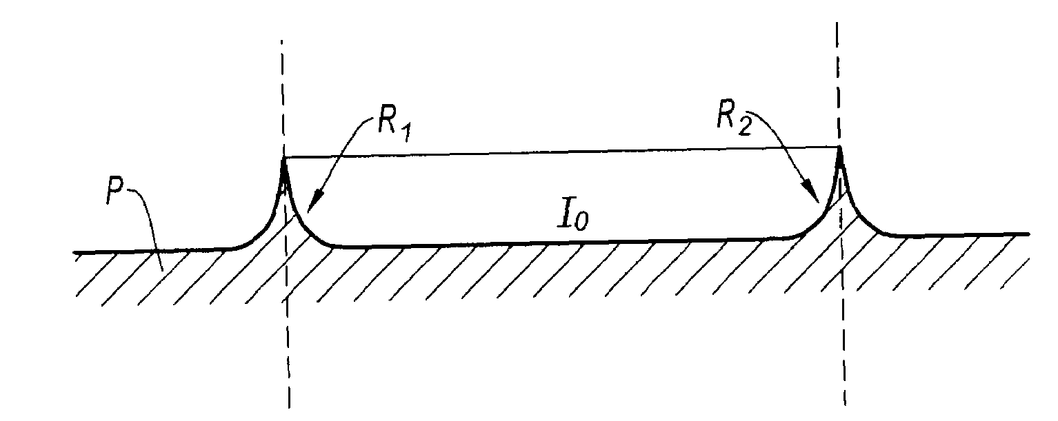
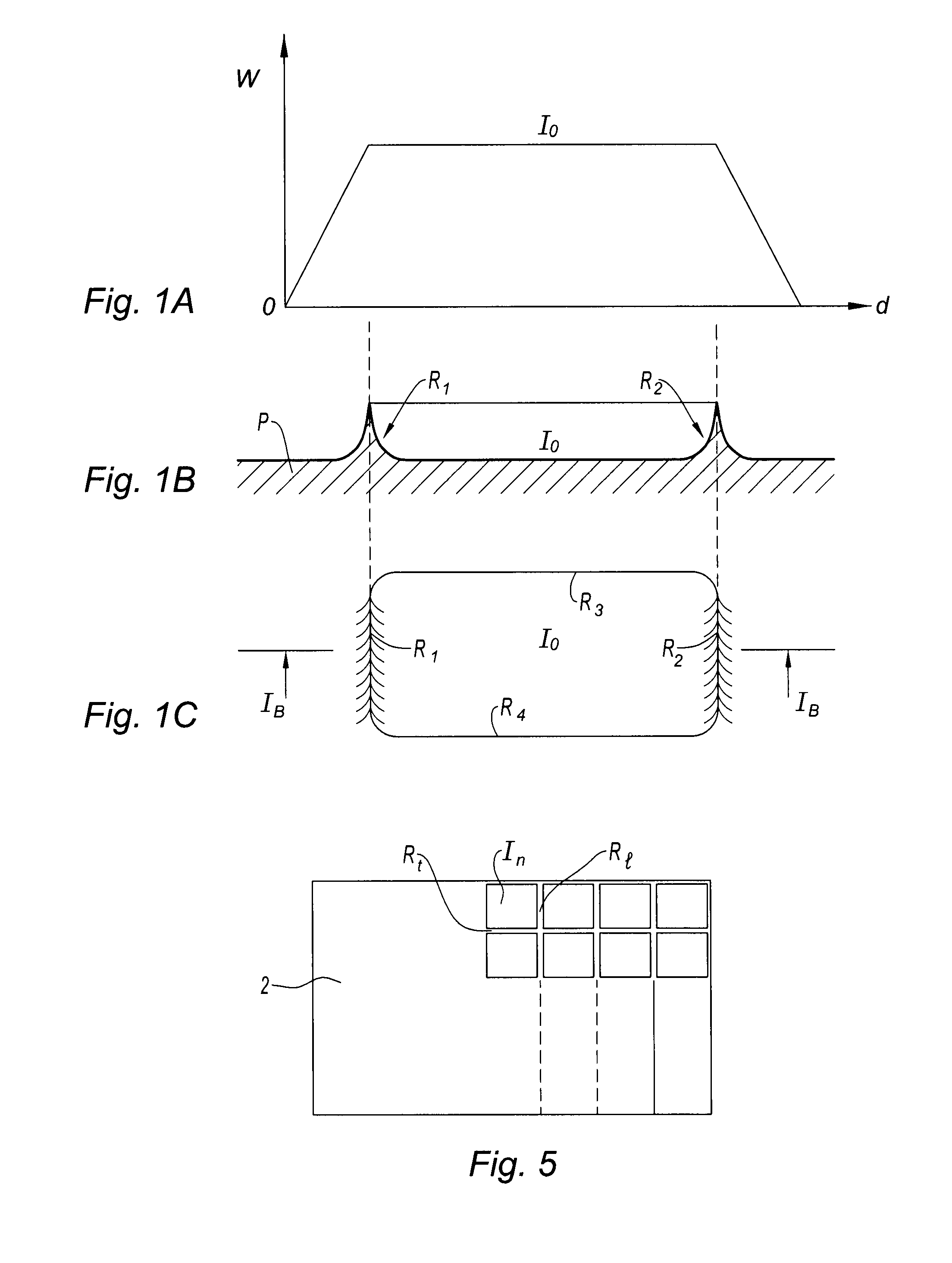
[0021]FIG. 1 is in three parts, 1A, 1B and 1C. The graph of FIG. 1A illustrates the energy variation W on the x axis applied across the impact, the y axis gives the distance d. It can be seen that the energy is uniform and maximal in the central zone of the impact I0. It diminishes progressively when further from the impact. In diagram 1B, which is a section of the part P in the impact zone I0 and shows its surface state, the material is pushed away to the edges of the impact I0 and forms lateral raised elements R1 and R2, seen in section. The height of the raised elements depends on the energy of the shock and the properties of the substrate receiving the laser shock.

[0022]In a top view, the shape of the zone deformed by the impact depends on that of the beam, in this instance the shape of the impact is rectangular. The deformed zone has the shape of a dish bordered by four low walls or raised elements R1, R2, R3 and R4.

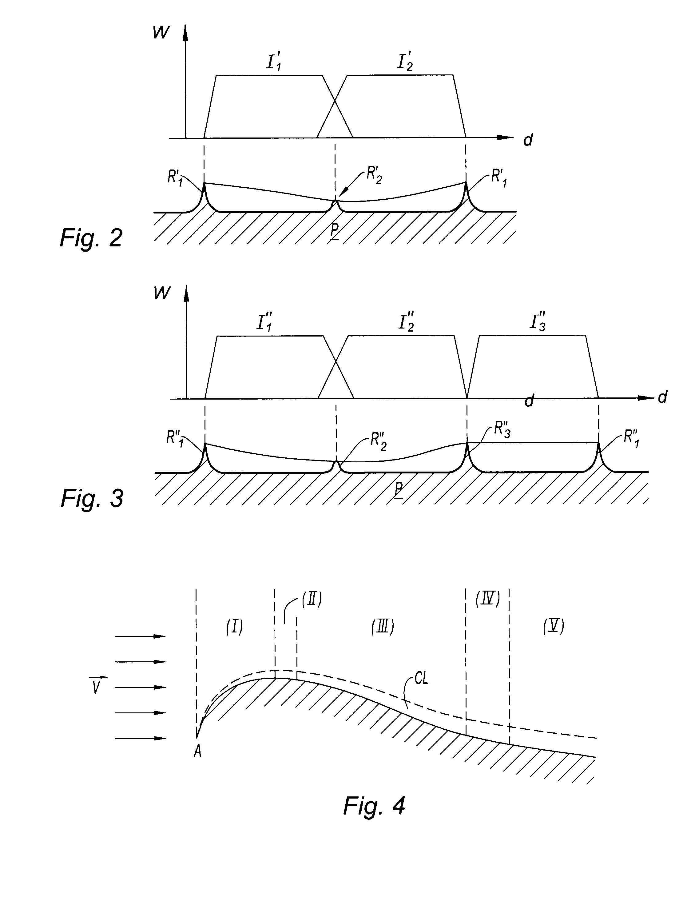
[0023]FIG. 2, like FIG. 1, shows a graph 2A and a section on F...


PUM

PropertyMeasurementUnit
surface areaaaaaaaaaaa
heightsaaaaaaaaaa
roughnessaaaaaaaaaa

Abstract

The present invention relates to a method for producing, on the surface of a wall capable of being swept by a fluid, raised elements forming disruptions of the boundary layer. It is characterized in that laser shocks are applied to said surface so as to create peaks on the edge of the impact zones, the peaks forming said disruptive raised elements.

Description

BACKGROUND OF THE INVENTION[0001]The present invention relates to the field of turbomachines and is aimed more particularly at a means for improving the flow of fluids along surfaces with an aerodynamic function, such as blades.DESCRIPTION OF THE PRIOR ART[0002]Studies show that the efficiency of a wing or of a blade is greatly improved by the polishing of its surface but that the organization of the roughness of the leading edge may have a not inconsiderable effect on the separation of the boundary layer on the suction surface. The calculations show that the creation of disruptions organized along the leading edge may, based on a polished state, further improve this efficiency. Tests on the “shark skin” effect have been carried out on aircraft wings and have shown a gain in specific fuel consumption CS of the order of 1%. The “shark skin” is produced from adhesive films of the Mylar® type.[0003]Furthermore, apart from these questions relating to aerodynamism, there is a search to i...

Claims


Application Information

Patent Timeline
Patent Type & Authority Applications(United States)
IPC IPC(8): B21D53/78B23K26/36
CPCB23K26/0069B23K26/0078B23K2201/001Y10T29/49336B21D53/78Y10T29/49863F15D1/12B23K26/3584B23K2101/001B23K26/356
Inventor LEBRET, YANN PASCAL RAYMOND RENEMONS, CLAUDE MARCEL
Owner SN DETUDE & DE CONSTR DE MOTEURS DAVIATION S N E C M A
Why Eureka
Try Eureka