Transparent Adhesive Tape

Inactive Publication Date: 2009-03-26
TESA SE
View PDF9 Cites 13 Cited by
  • Summary
  • Abstract
  • Description
  • Claims
  • Application Information

AI Technical Summary

Benefits of technology

[0013]It is an object of the present invention, therefore, to provide an exclusively unilaterally bondable, substantially two-dimensional element that eliminates these drawbacks, which can be employed more particularly as a cost-effective, high-transparency functional film in the production of transparent laminated protective windows of variable form, and so permits simple production of display systems with a transparent sightpath.

Problems solved by technology

Hence polymer screens are inexpensive, easy to process, and offer efficient protection from mechanical influences, but have the drawback that they are typically not scratch-resistant and are therefore easily damaged.
After just a short time this not only results in a deterioration in the aesthetic impression of the display systems but also has the consequence, furthermore, of a reduced view of the display area of the display modules.
Moreover, many common polymers have only limited resistance to ultra-violet light (UV light) or to organic solvents.
Owing to the brittleness of this material, resulting from its hardness, however, glass is of only limited suitability as a protection against mechanical influences such as impact or strike, since even weak stresses may be accompanied by fragmentary brittle fracture of the glass screen.
As well as the limited protection effect, therefore, there is a risk of injury from the shards that are produced, and also the risk of damage to the display module by sharp-edged fragments.
For non-stationary applications, however, laminated glass of this kind is a disadvantage on account of its high weight and relatively expensive manufacture.
A laminated protective window of this kind, however, is not fully transparent, but instead typically contains defects which reduce the intensity of the light passing through the protective window.
This represents a problem more particularly in the case of low-contrast displays, since the viewer is then unable to make out adequately the information reproduced on the display array, owing to the low light intensity.
This is the case, for instance, with all of those display systems which are employed in inadequately darkened environments—as, for example, portable handheld computers outdoors under direct sunlight—and also in the case of display systems which for technical reasons have only a low contrast, examples being liquid-crystal displays with low energy consumption which do not have any self-illuminating backlight elements but instead exclusively reflect the ambient light incident from their exterior.

Method used


Image

  • Transparent Adhesive Tape
  • Transparent Adhesive Tape
  • Transparent Adhesive Tape

Examples


Embodiment Construction

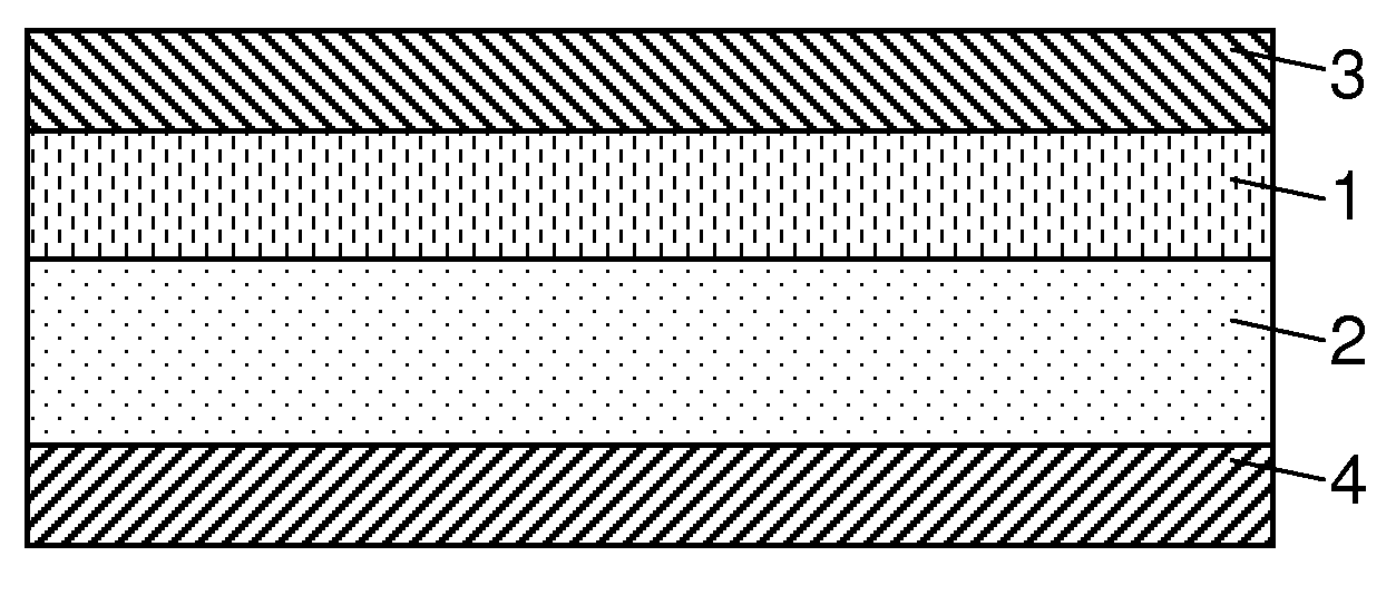
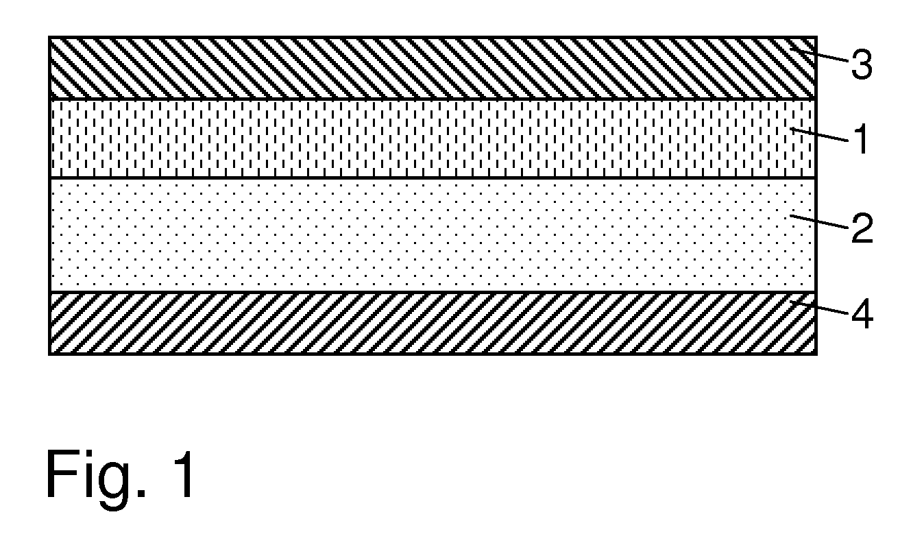
[0242]The first construction embodiment of the 2D element, shown in FIG. 1, has as its second functional layer a support 1 which is in the form of a polymer film; its adhesive coating 2 is an acrylate-based pressure-sensitive adhesive; its first functional layer is an adapter in the form of an antireflection coating 3; and its temporary support 4 is a siliconized release film. The support film 1 is covered uniformly and over its full area on one side face with the pressure-sensitive adhesive 2. Disposed on the other side face of the support 1 is the antireflection coating 3. Here, therefore, the antireflection coating 3 is disposed between the support 1 and the surrounding medium. To protect against contamination and against unwanted bonding with the release film, the adhesive 2 is covered over its full area with the temporary support 4.

[0243]The second construction embodiment of the 2D element, shown in FIG. 2, possesses substantially the same fundamental construction as the constr...


PUM

PropertyMeasurementUnit
Thicknessaaaaaaaaaa
Thicknessaaaaaaaaaa
Thicknessaaaaaaaaaa

Abstract

A construction is presented for a unilaterally bondable, high-transparency, substantially two-dimensional element (2D element) having a support and an adhesive, which is used as a shatterproofing device for brittle 2D bodies.

Description

BACKGROUND OF THE INVENTION[0001](1) Field of the Invention[0002]The invention is situated within the field of applied polymer engineering and relates to an exclusively unilaterally bondable, substantially two-dimensional element (2D element) comprising a sheetlike first functional layer, a sheetlike second functional layer and a sheetlike adhesive coating, one of the two functional layers being designed as a support and the other of the two functional layers being designed as an adapter, the second functional layer having, parallel to its principal extent, first and second side faces, the first functional layer being disposed on the first side face of the second functional layer, and the adhesive coating being disposed on the second side face of the second functional layer and being adapted for permanent joining of the 2D element to a brittle 2D body which is to be held together by means of the 2D element in the event of fracture. The invention further relates to an adhesively bond...

Claims


Application Information

Patent Timeline
IPC IPC(8): B32B7/02C09J7/29C09J7/38
CPCB32B17/10009C09J7/0207C09J7/0296C09J9/00Y10T428/24942C09J2433/00C09J2453/00G02F2202/28C09J2201/622C09J7/38C09J7/29C09J2301/312
Inventor HUSEMANN, MARCDALMIS, GABRIEL
Owner TESA SE
Why Eureka
Try Eureka