
Voltage mode pwmff-pfm/skip combo controller

Inactive Publication Date: 2009-03-26
MICRO DC
View PDF8 Cites 40 Cited by
  • Summary
  • Abstract
  • Description
  • Claims
  • Application Information

AI Technical Summary

Benefits of technology

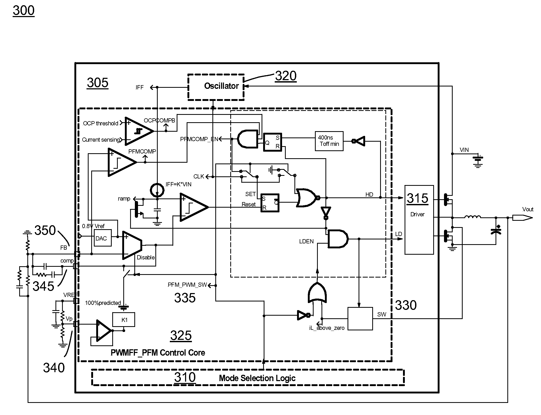
[0007]An embodiment of a controller has the following features: At heavy load, the controller operates as a fixed frequency voltage-mode PWM controller with feed-forward, improving noise immunity, providing good efficiency from small to high load, and good dynamic response. At light load, the controller switches over to pulse frequency modulation (PFM). A benefit of this controller is that the frequency is linearly dependent on the load, when the load is small, the switching frequency is reduced, significantly improving the efficiency at light load. This makes this controller especially suitable for a portable or notebook applications.
[0008]A simple architecture of an oscillator embodiment to provide the feed-forward function is shown in FIG. 4. This architecture allows the oscillation ramp to be proportional to VIN without changing the frequency. It also allows programmable frequency with an external resistor.
[0009]In an embodiment of the controller (e.g. FIG. 3), at heavy load, the system operates in voltage mode PWM control, and the error amplifier controls the regulation. At light load, the system will switch to PFM mode. In PFM mode, in an embodiment, a clamp circuit clamps the error amplifier output to a predicted value. This clamped value is very close to the real voltage in the application. This benefit is that the output does not have a big droop when a load suddenly changes from light load to heavy load, when load. When the system changes from light load to heavy load the system will switch back to PWM mode. In other words, in an embodiment, a clamp circuit provides that the system will go back to PWM mode smoothly.
[0012]To avoid chattering when the system transfers from one mode to the other mode (e.g. PWM to PFM); hysteresis is added, as shown in FIG. 7.
[0013]A PWM / SKIP controller embodiment that can work with ceramic output capacitors is also described as shown in FIGS. 23 and 24 and demonstrated in FIG. 25. This embodiment allows the use of ceramic output capacitors which is popular in portable application such as cell phones, etc. The concept is to limit the error amplifier such that the output can not be lower than 70% or some other percentage of predicted value. As a result, at light load, the output will keep increasing and once Vout is above 3% or some percentage of nominal voltage, the system will shut off and will go into low current mode. The state graph is shown in FIG. 24. This provides high efficiency at light load. The predicted error amplifier output is calculated based on VIN and the desired VOUT. This provides a high efficiency operation over the entire load range and still guarantees output regulation.
[0014]An advantage of PWM / SKIP mode is also that the whole controller is controlled by the error amplifier and the skip comparator. At light load, the system operates with a few cycles of PWM operation with fixed frequency. Then, it shuts off and relies on the load to discharge the output. As a result, efficiency is higher. No PFM Comparator is used. This eliminates the sensitivity of PFM control (pulse frequency control) without sacrificing efficiency.

Problems solved by technology

Electronics components are becoming increasingly complex and miniaturized.
However, benefits of low power consumption can be lost if the accompanying DC power supplies are inefficient.
While suitable for some purposes, these traditional controllers have disadvantages.
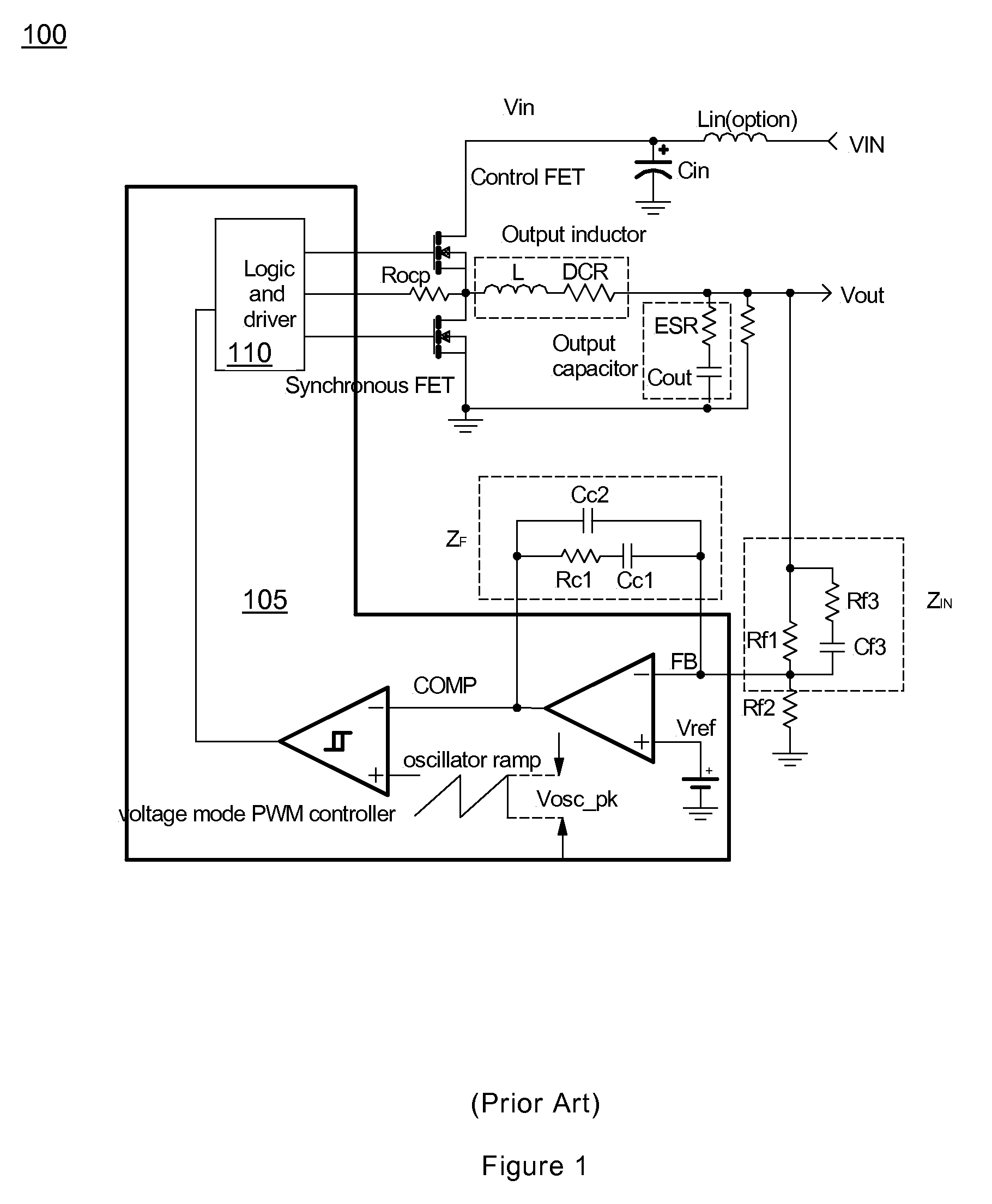
Drawbacks of traditional voltage mode PWM controllers include poor response with input voltage response, input voltage dependent system bandwidth, and poor efficiency at light load.

Method used


Image

  • Voltage mode pwmff-pfm/skip combo controller
  • Voltage mode pwmff-pfm/skip combo controller
  • Voltage mode pwmff-pfm/skip combo controller

Examples


Embodiment Construction

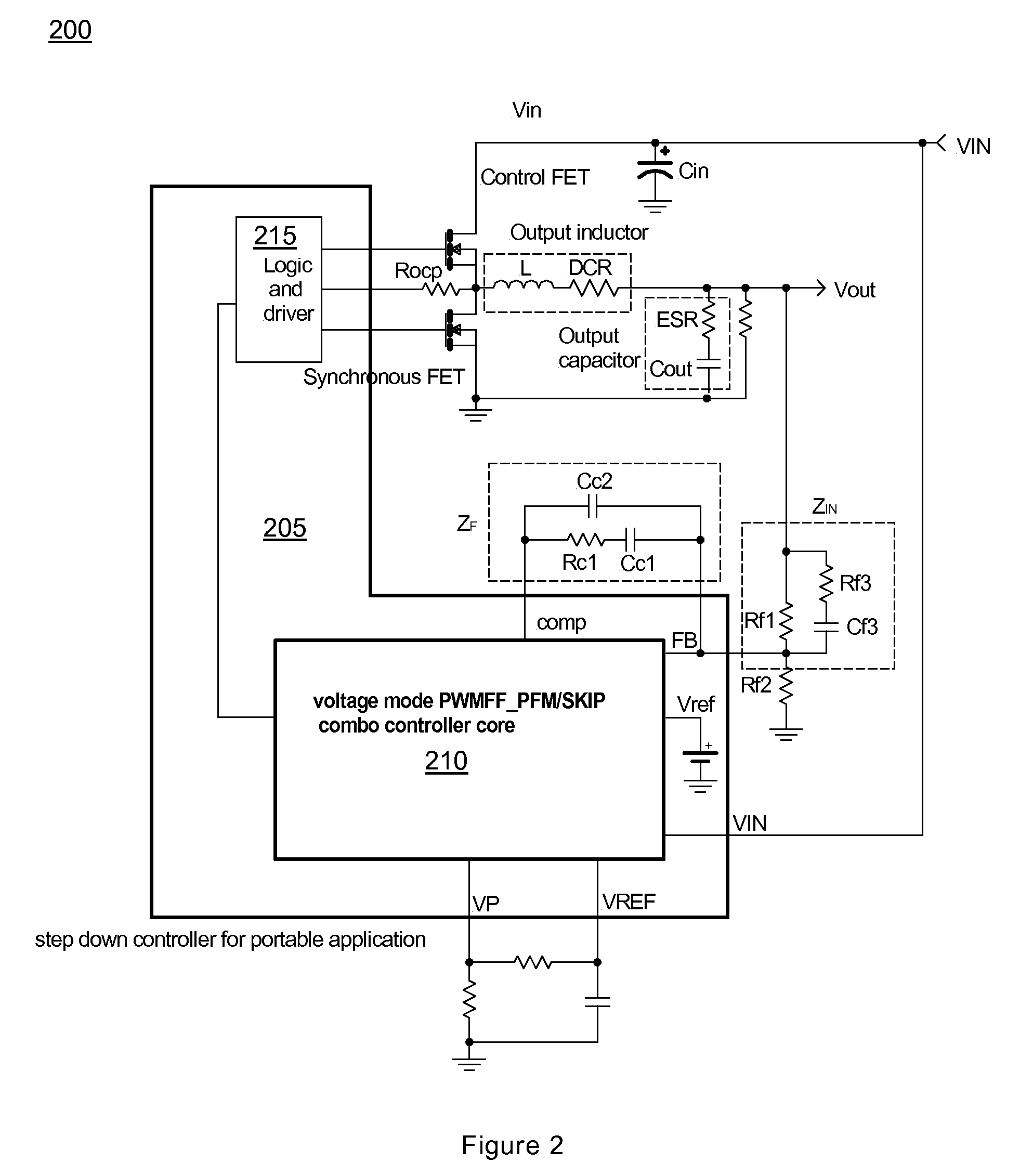
[0047]Circuit figures portray embodiments of the invention shown in systems and components of the invention. Features of embodiments include integrated MOSFET components, hysteresis, oscillator feed-forward, fixed gain, error amplifier (EA) limits, and SKIP mode operation. Particularly, FIG. 2 displays an embodiment of the invention in a portable system and FIG. 3 displays more detail of a combo controller core shown in FIG. 2. FIG. 4 displays more detail of an oscillator shown in FIG. 3, and FIG. 5 displays more detail of mode selection logic shown in FIG. 3. FIG. 8 is an embodiment of the controller shown in FIG. 3 with added, integrated, MOSFET components. Figures that include oscilloscope displays primarily portray operation of embodiments of the invention. Again, particularly, FIGS. 9 through 11C display waveforms from the embodiment of FIG. 3. FIGS. 11A-11C portray operation of embodiments of FIG. 3 during a load transient. FIGS. 12 and 13 are graphs of measured data.

[0048]FIG...


PUM


Abstract

A voltage controller and method providing multiple modes of operation. Embodiments include pulse-width modulation (PWM), feed-forward (FF), pulse-frequency modulation (PFM) and skip operation (PWM-FF-PFM / SKIP). Controller embodiments have integrated MOSFET components, comparator hysteresis, oscillator feed-forward, fixed gain, and error amplifier (EA) limits thereby providing improved efficiency and noise immunity.

Description

RELATED APPLICATIONS[0001]This application claims the benefit of U.S. Provisional Application No. 60 / 974,160 filed Sep. 21, 2007. This application is herein incorporated in its entirety by reference.FIELD OF THE INVENTION[0002]The invention relates to voltage regulators and, more specifically, to pulse-width modulation (PWM) feed-forward (FF) pulse-frequency modulation (PFM) PWMFF-PFM / SKIP controller systems and methods.BACKGROUND OF THE INVENTION[0003]Electronics components are becoming increasingly complex and miniaturized. Accompanying this progress is decreased power consumption. However, benefits of low power consumption can be lost if the accompanying DC power supplies are inefficient. Efficiencies can be improved through controller design. Voltage mode pulse-width modulation (PWM) controllers have been widely used in the power industry in many applications including in motherboards, VGA cards, DC to DC converters. While suitable for some purposes, these traditional controller...

Claims


Application Information

Patent Timeline
IPC IPC(8): G05F1/46
CPCH02M3/157Y02B70/1466H02M3/1588Y02B70/10
Inventor QIAO, CHONGMINGAMIRANI, REZACONDITO, VINCENTASVADI, AMIR
Owner MICRO DC
Learn More