Motor controller and electric power steering apparatus

a technology of motor controller and electric steering apparatus, which is applied in the direction of motor/generator/converter stopper, dynamo-electric gear control, dynamo-electric converter control, etc., can solve the problems of torque ripple, preventing the motor controller from performing appropriately, and not necessarily equal phase values, etc., to achieve the effect of reducing the torque ripple and increasing the calculation load

Inactive Publication Date: 2009-03-26
JTEKT CORP
View PDF40 Cites 26 Cited by
  • Summary
  • Abstract
  • Description
  • Claims
  • Application Information

AI Technical Summary

Benefits of technology

[0006]Accordingly, it is an objective of the present invention to provide a motor controller and an electric power steering apparatus that suppress a torque ripple caused by unequal resistance values of phases, without increasing calculation load.
[0007]To achieve the foregoing objective and in accordance with a first aspect of the present invention, a motor controller having signal generating means that generates a motor control signal by performing an electric current feedback control in a d-q coordinate system, and a driver circuit that supplies a drive power of three phases to a motor based on the motor control signal is provided. The motor controller includes memory means that stores a resistance value of each one of the phases of the motor. The signal generating means corrects respective voltage command values of the d-q coordinate system based on the stored resistance values in such a manner as to suppress a torque ripple caused by a difference among the resistance values.

Problems solved by technology

However, in reality, the resistance values of the phases are not necessarily equal due to different lengths of cables or vary depending on whether failsafe phase opening relays are provided for the phases.
This results in unequal electric currents flowing in the phases, causing a torque ripple.
This prevents the motor controller from performing appropriately if the resistance values of the phase opening relays are varied or the lengths of the cables are unequal among the phases.
However, this increases calculation load and requires the use of a calculation device (a microcomputer) with higher performance, which raises the manufacturing cost.

Method used


Image

  • Motor controller and electric power steering apparatus
  • Motor controller and electric power steering apparatus
  • Motor controller and electric power steering apparatus

Examples


Embodiment Construction

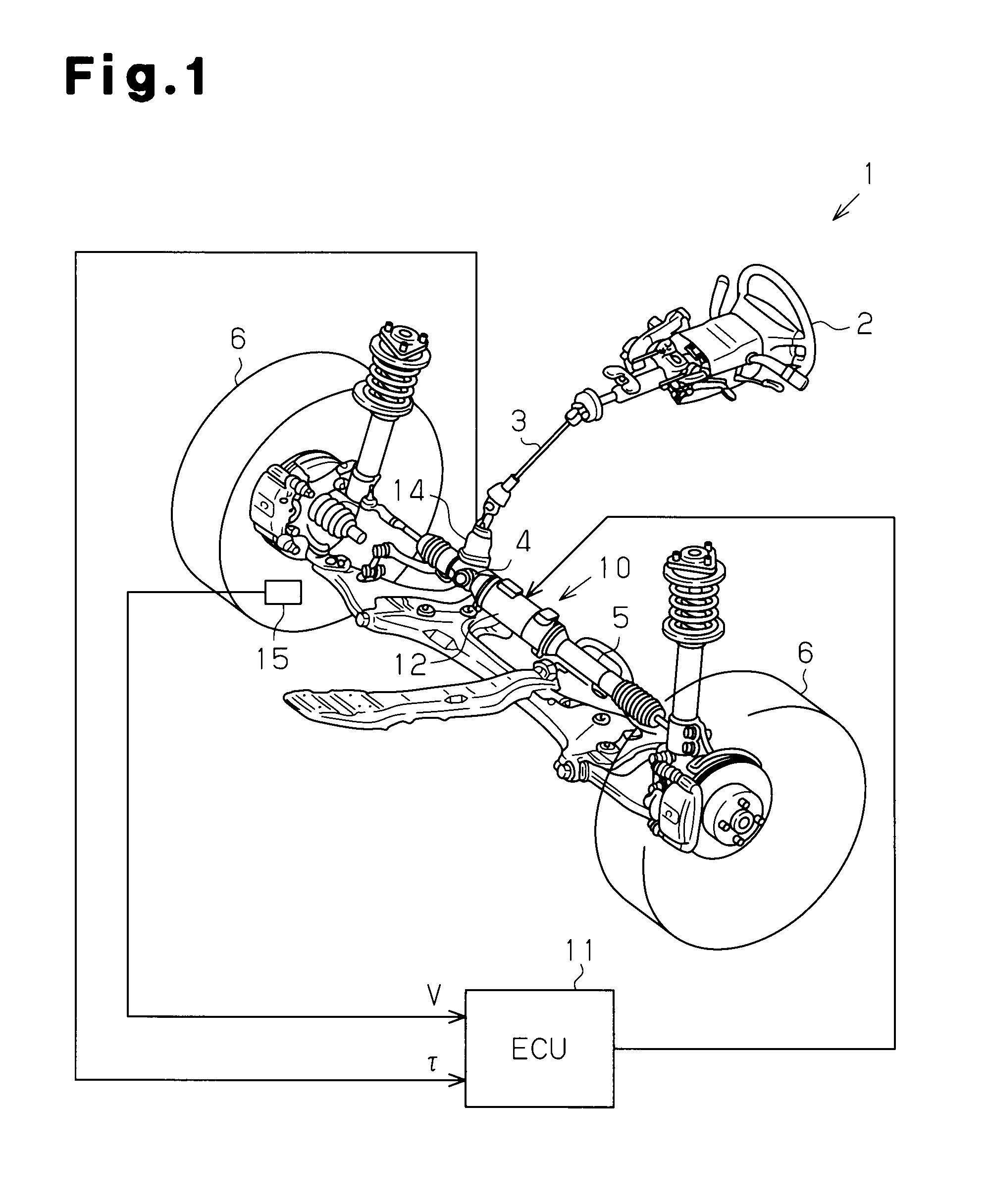
[0015]An embodiment of the present invention, which is an electric power steering apparatus (an EPS), will now be described with reference to the attached drawings.

[0016]As shown in FIG. 1, a steering wheel 2 is fixed to a steering shaft 3. The steering shaft 3 is connected to a rack 5 through a rack-and-pinion mechanism 4. The steering shaft 3 is rotated through steering. The rotation of the steering shaft 3 is converted into linear reciprocation of the rack 5 through the rack-and-pinion mechanism 4. This changes steering angles of steerable wheels 6.

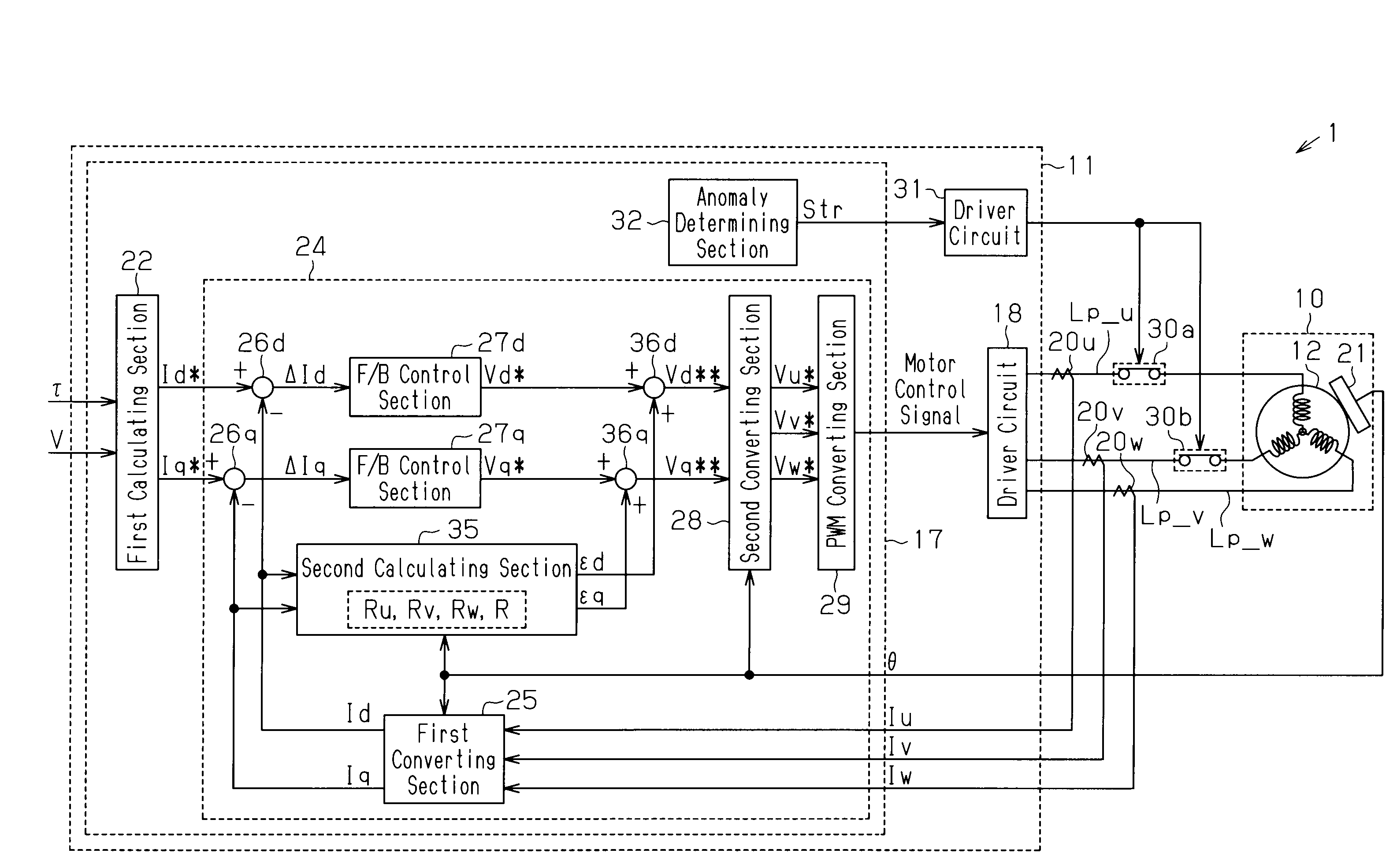
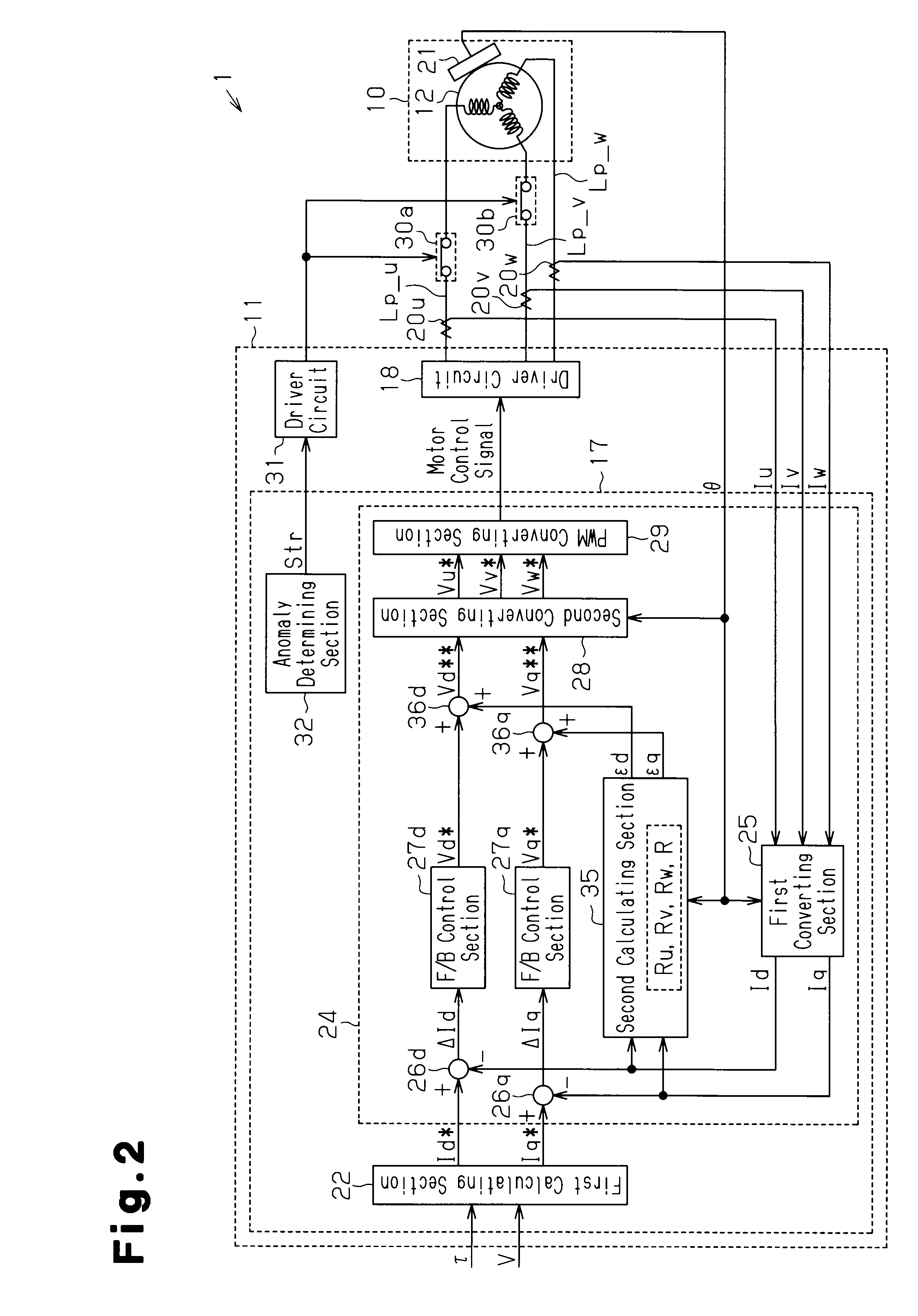
[0017]An EPS 1 has an EPS actuator 10 and an ECU 11. The EPS actuator 10 is a steering force assisting device that applies assist force to a steering system in order to assist steering. The ECU 11 is control means that controls operation of the EPS actuator 10.

[0018]The EPS actuator 10 is a rack type EPC actuator and is powered by a motor 12, or a drive source, which is arranged coaxially with the rack 5. In the EPS actuator 10, the mo...


PUM


Abstract

A signal generating section includes a second calculating section that corrects phase resistance. The calculating section stores resistance values of phases that have been measured in advance and a reference resistance value. The calculating section calculates correction components, which cancel a voltage drop term of a voltage equation of a d-q coordinate system changing depending on the rotation angle of the motor, based on the stored resistance values and the reference resistance value. The signal generating section superimposes the correction component and the correction component on a d-axis voltage command value and a q-axis voltage command value, respectively. The d-axis voltage command value and the q-axis voltage command value are thus corrected in such a manner as to suppress a torque ripple caused by difference among the resistance values of the phases.

Description

[0001]This application is based on and claims priority from Japanese Patent Application No. 2007-249612 filed on Sep. 26, 2007, the entire contents of which are incorporated herein by reference.BACKGROUND OF THE INVENTION[0002]The present invention relates to a motor controller and an electric power steering apparatus.[0003]Conventionally, a motor controller that controls a motor through supply of drive power of three phases (U, V, and W-phases) to the motor operates on the presumption that the resistance values of the phases are equal. Thus, on such presumption, the motor controller adjusts the voltages supplied to the phases in such a manner that the amounts of the electric currents flowing in the phases become equal. In other words, the motor controller adjusts the voltages supplied to the phases in such a manner that the waveforms of the electric currents of the phases have equal amplitudes and the sum of the electric currents of the phases at a common rotation angle becomes zer...

Claims


Application Information

Patent Timeline
Patent Type & Authority Applications(United States)
IPC IPC(8): H02P21/14B62D5/04H02P6/06H02P6/08H02P6/28H02P21/00H02P21/05H02P21/22H02P23/04H02P23/07H02P27/04
CPCH02P21/145H02P21/16H02P29/0241
Inventor SUZUKI, HIROSHI
Owner JTEKT CORP
Why Eureka
Try Eureka