
Pneumatic tire

a technology of pneumatic tires and tires, which is applied in the direction of vehicle components, transportation and packaging, non-skid devices, etc., can solve the problems of achieve the effect of inhibiting easy deflecting, and not extremely lowering the rigidity of the land portion

Active Publication Date: 2009-03-26
TOYO TIRE & RUBBER CO LTD
View PDF4 Cites 19 Cited by
  • Summary
  • Abstract
  • Description
  • Claims
  • Application Information

AI Technical Summary

Benefits of technology

[0009]The present invention is made by taking the actual condition mentioned above into consideration, and an object of the present invention is to provide a pneumatic tire which can secure an edge effect and a drainage effect generated by a sipe, by securing a rigidity of a land portion so as to prevent an excessive collapse while inhibiting an opening portion of the sipe from being narrowed.
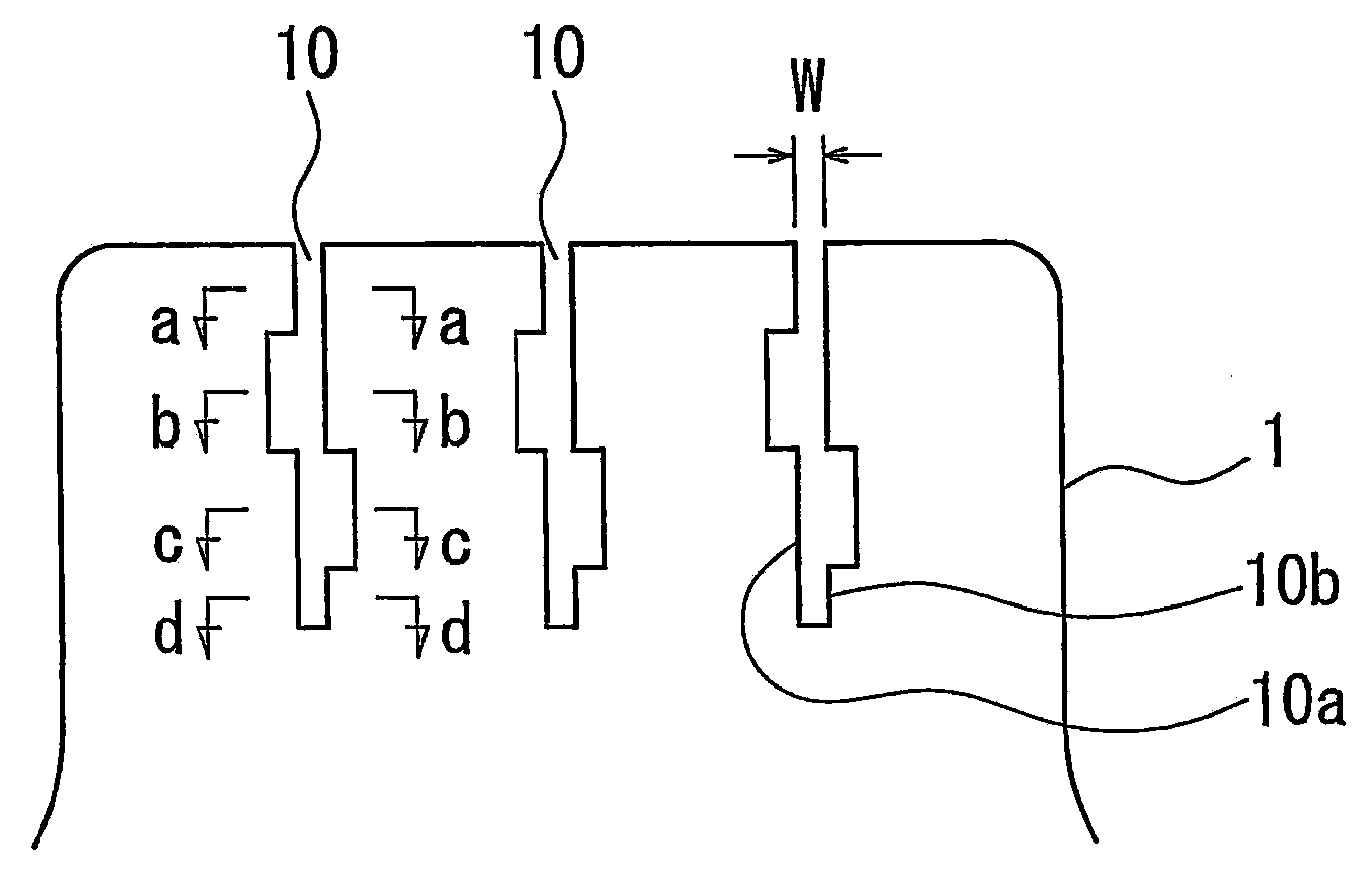
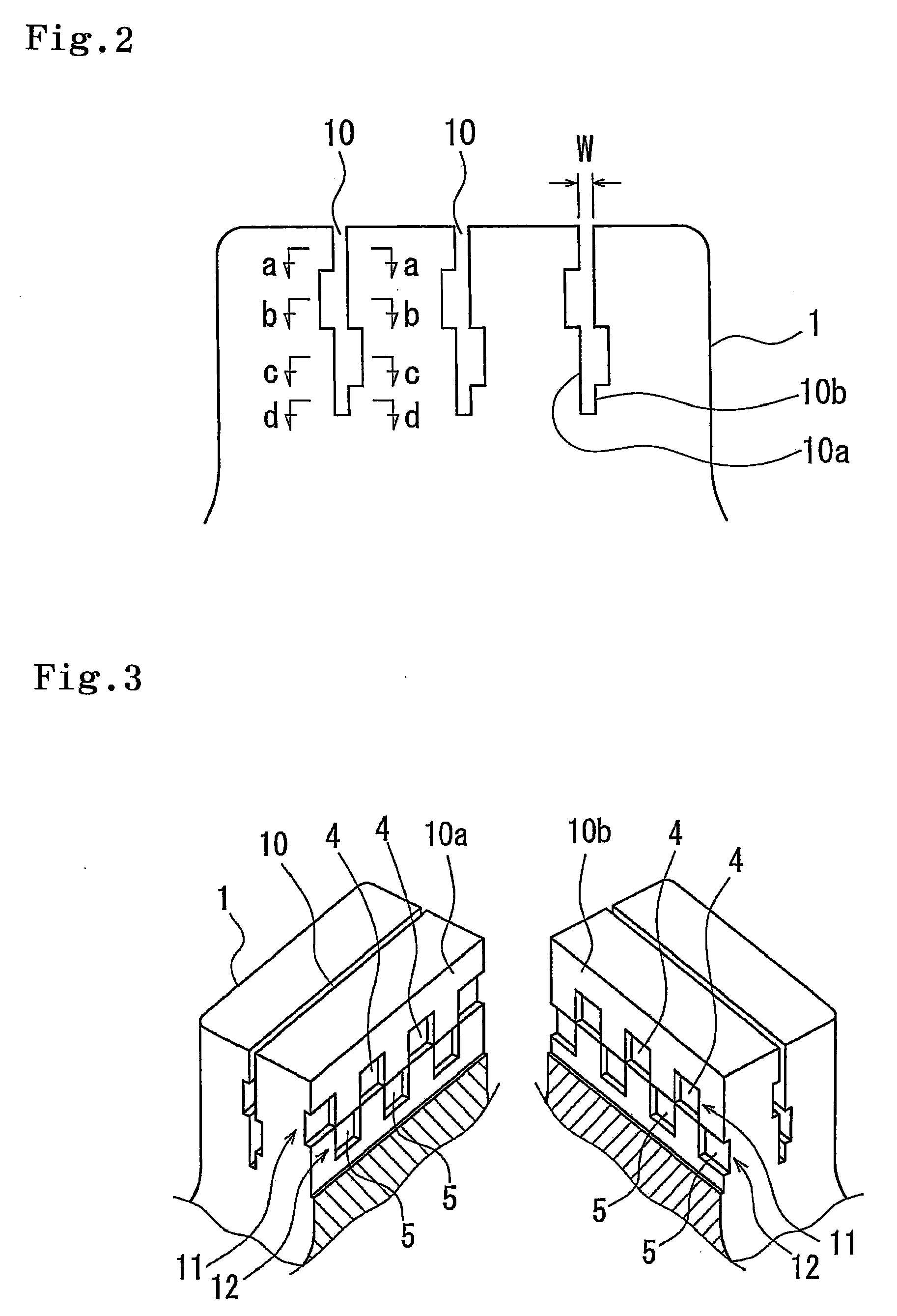
[0011]In the pneumatic tire in accordance with the present invention, since the wide portion is constituted by a plurality of concave portions as mentioned above, the portion having the large sipe width is intermittently formed short in the longitudinal direction, in each of the sipe wall surfaces. Accordingly, it is possible to inhibit the rigidity of the land portion from being lowered by the wide portion. Even if a wear makes progress and the wide portion appears on the tread surface, the rigidity of the land portion is not extremely lowered. Further, since the concave portion mentioned above is arranged alternately in both sides of the sipe wall surface, whereby the wide portion along the longitudinal direction is constructed, it is possible to make the tread rubber be easily deflected in the depth direction, and it is possible to absorb the deformation by the wide portion so as to inhibit the opening portion from being narrowed. As a result, it is possible to secure the edge effect and the drainage effect generated by the sipe so as to improve the ice performance.
[0012]In the structure mentioned above, it is preferable that the sipe has the wide portion at a plurality of positions in the depth direction, and the concave portions which are adjacent to each other in the depth direction are concaved in inversed directions to each other. Since the sipe has the wide portion at a plurality of positions in the depth direction, it is possible to improve the effect of absorbing the deformation by the wide portion so as to inhibit the opening portion from being narrowed. Further, since the concave portions which are adjacent in the depth direction are concaved in an inverse direction, a rigidity balance of the land portion becomes good, and it is possible to effectively suppress the excessive collapse of the land portion.

Problems solved by technology

Even if a wear makes progress and the wide portion appears on the tread surface, the rigidity of the land portion is not extremely lowered.

Method used


Image

  • Pneumatic tire
  • Pneumatic tire
  • Pneumatic tire

Examples


example

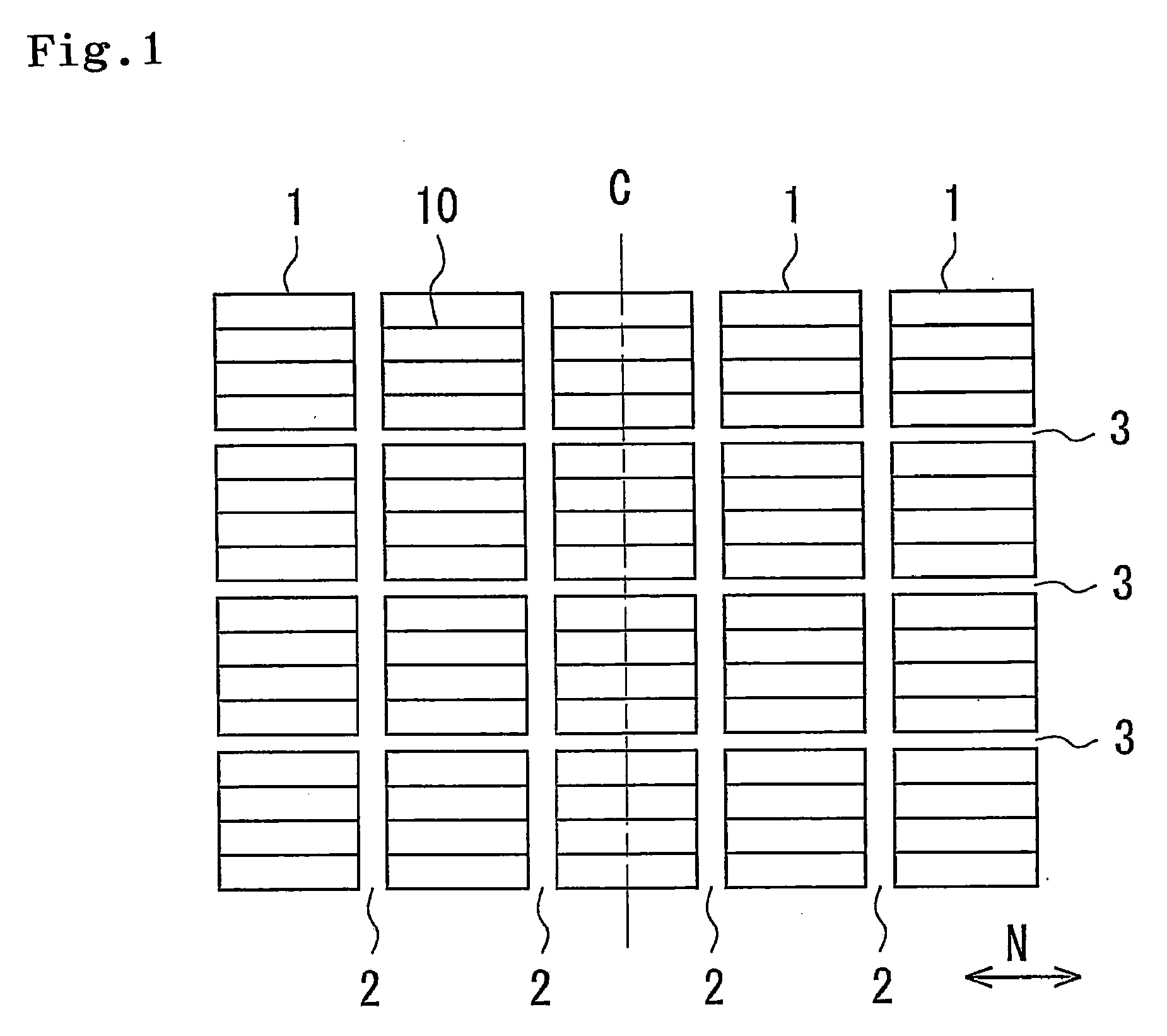
[0050]An example is set to a tire having a tread pattern as shown in FIG. 1 and forming a sipe having a wide portion shown in FIGS. 2 to 5 in a block. A tire size is set to 205 / 65R15, a sipe depth D is set to 6.5 mm, a depth of each of the wide portions is set to 2 mm, a depth of a non-wide portion close to the tread surface is set to 1.5 mm, a sipe width W is set to 0.3 mm, and a thickness of each of concave portions is set to 0.3 mm. Results of the evaluation are shown in Table 1.

TABLE 1Comparative ExampleExampleIce braking100107performanceIce turning100107performance

[0051]In spite that a total volume of the wide portion is identical between the comparative example and the example, the ice braking performance and the ice turning performance are improved in the example in comparison with the comparative example, as shown in Table 1. It is thought that the example can inhibit the rigidity of the land portion from being lowered in comparison with the comparative example, and the edge...


PUM


Abstract

A pneumatic tire structured such that a sipe is formed in a land portion of a tread surface. The sipe has a wide portion extending along a longitudinal direction at least at one position in a depth direction. The wide portion is structured by alternately arranging concave portions which are smaller in the longitudinal direction and the depth direction than the sipe, in both sides of a sipe wall surface along the longitudinal direction of the sipe.

Description

FIELD OF THE INVENTION[0001]The present invention relates to a pneumatic tire in which a sipe is formed in a land portion of a tread surface, and is particularly useful as a studless tire.DESCRIPTION OF THE RELATED ART [0002]Conventionally, in the studless tire, a cut called as the sipe is formed in the land portion of a block, a rib or the like, and a traveling performance (hereinafter, called as an ice performance) on an ice road surface having a low friction coefficient is increased by an edge effect and a drainage effect generated by the sipe. As the sipe mentioned above, there have been put to a practical use a linear sipe extending linearly along a longitudinal direction, a waveform sipe extending like a waveform and the like.[0003]Since a rubber is incompressible, a motion of the tread surface being in contact with the road surface becomes great in the case that a load is applied to the tire, so that an opening portion of the sipe tends to be closed. Particularly, since the t...

Claims


Application Information

Patent Timeline
IPC IPC(8): B60C11/00
CPCB60C11/12B60C11/1281B60C2011/1209B60C11/1218
Inventor OHASHI, TOSHIYUKI
Owner TOYO TIRE & RUBBER CO LTD
Learn More