
Integrated resource monitoring system with interactive logic control

Inactive Publication Date: 2009-03-19
GROUNDSWELL TECH INC
View PDF36 Cites 26 Cited by
  • Summary
  • Abstract
  • Description
  • Claims
  • Application Information

AI Technical Summary

Benefits of technology

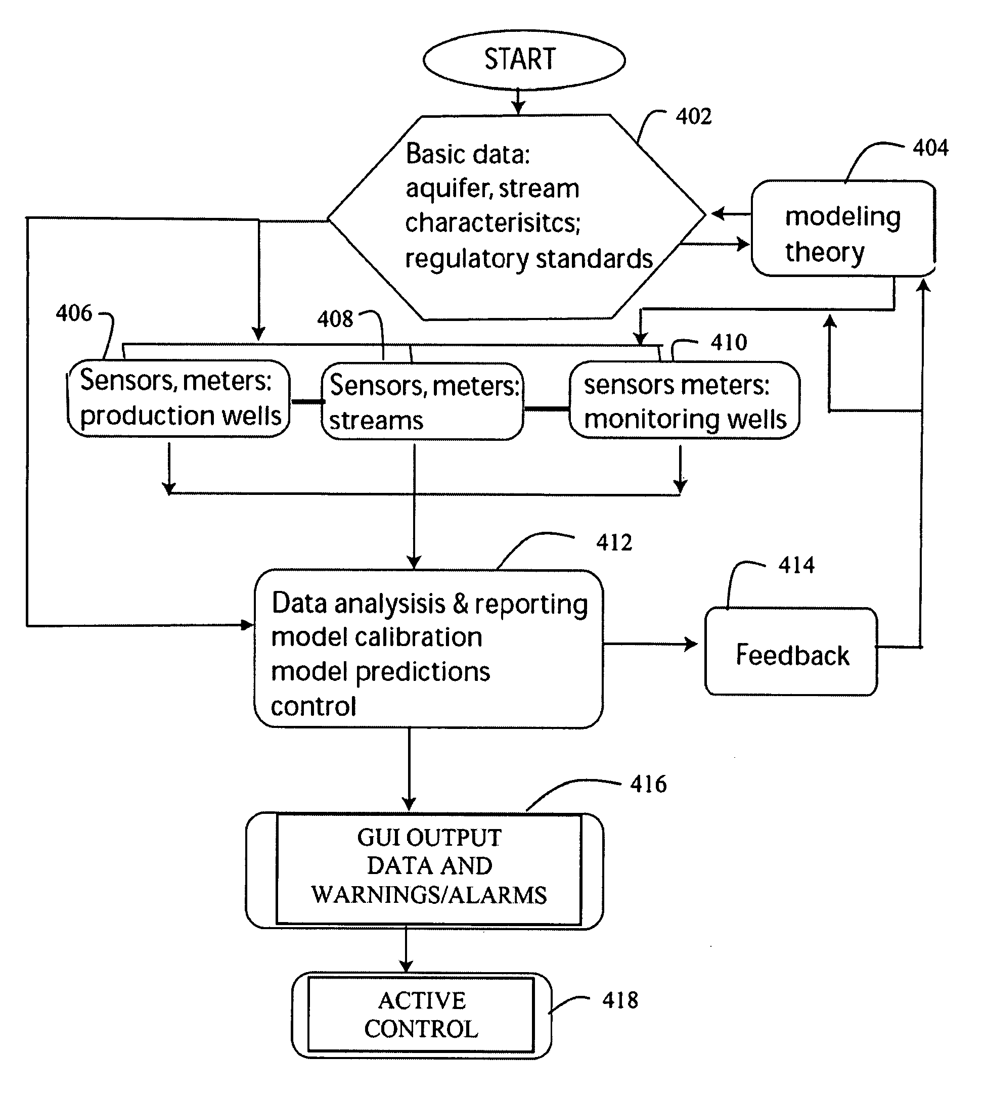
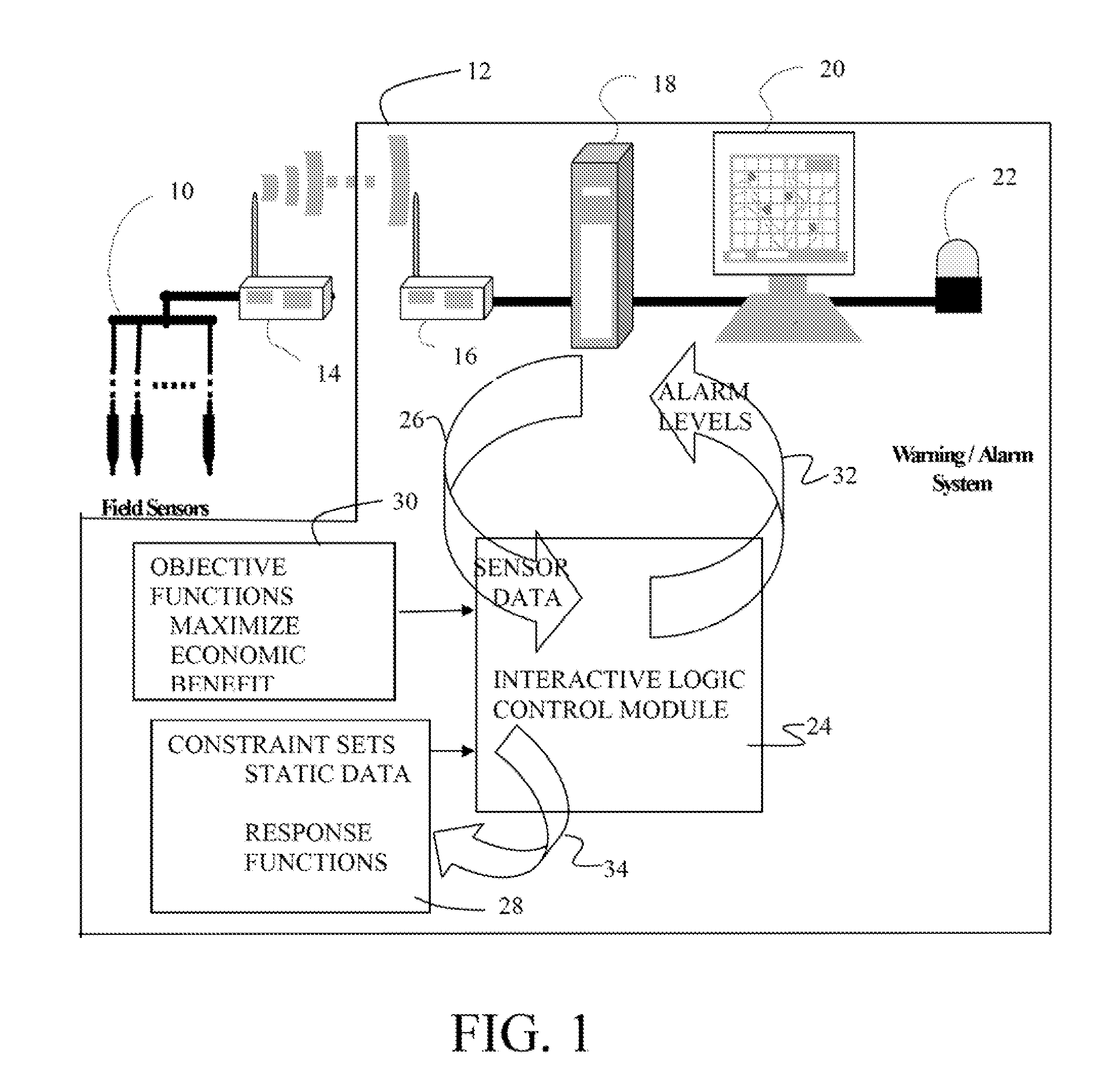
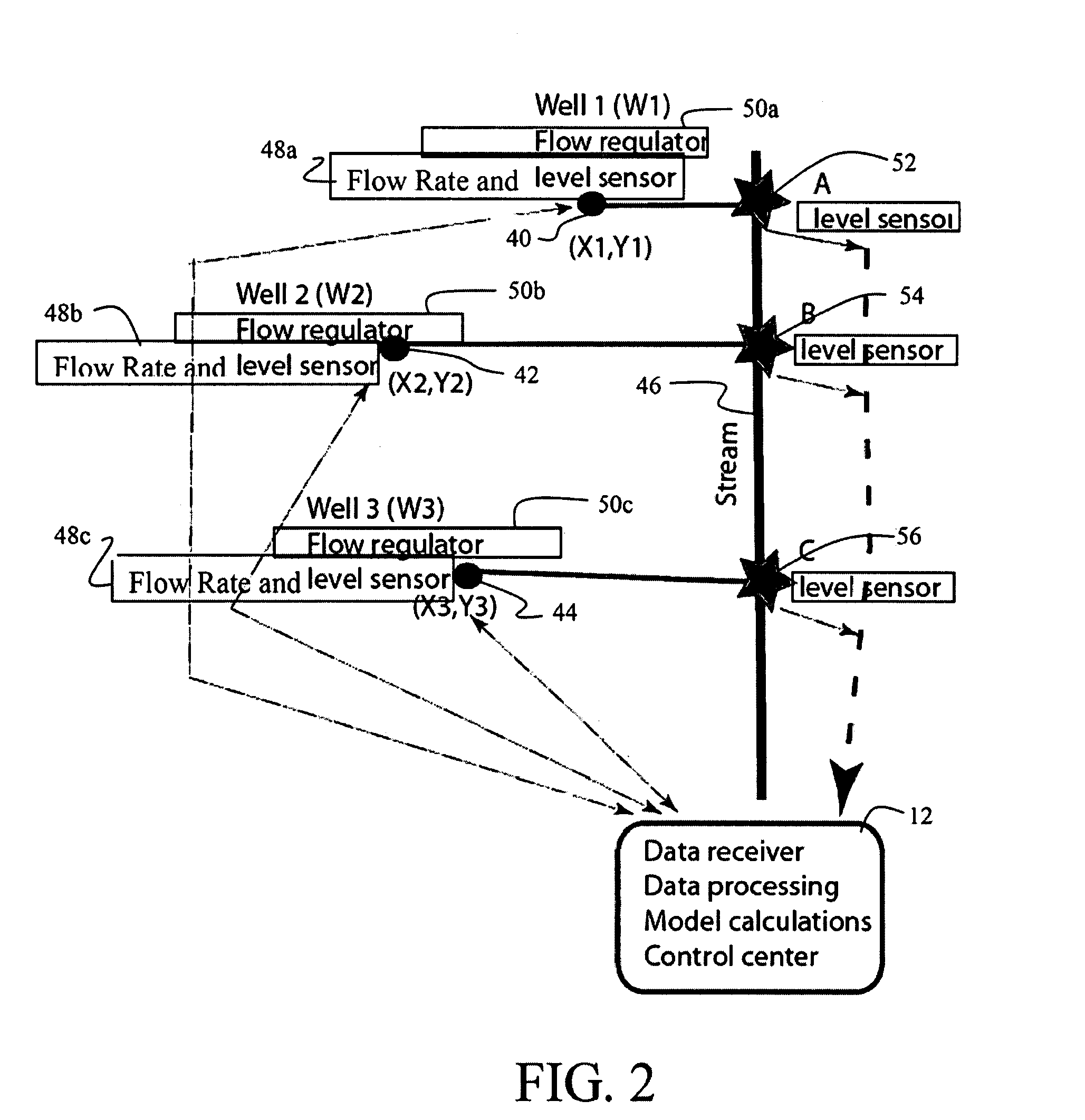
[0010]As an exemplary embodiment, a system incorporating the invention is employed for well water monitoring on one or multiple wells drawn upon for either municipal or agricultural use by multiple users. The objective functions for the interactive logic modeling system allow maximizing the water withdrawal capability in the most economically efficient manner by multiple users while avoiding salt water intrusion into the well from overdraw conditions or exceeding a river water level minimum, the latter relying of coupled dynamic interaction algorithm for well-stream systems. The constraint sets preloaded into the model include response of the aquifer modeled from static data including historical permeab

Problems solved by technology

U.S. Government Accountability Office, Freshwater Supply: States' Views of How Federal Agencies Could Help Them Meet the Challenges of Expected Shortages,” GA 0-03-514, July 2003, p 1)]Since many water supply well fields are installed adjacent to areas of shallow surface water, significant impairment to adjacent riparian habitat can result from ground water extraction activities.
Reduction in the ground water potentiometric surface due to over-pumping can induce leakage of the surface water body, thereby reducing the total amount of flow in rivers, streams, and springs.
Stream flow reduction during fish migration seasons threatens the species survival potential.
Otherwise, according to the Commonized Costs-Privatized Profits (or CCPP) paradox, there is a natural tendency towards non-cooperation and non-sustainable aquifer mining, of which overdraft is a typical symptom.
Non-cooperative behavior arises when at least one ground water user neglects the externalities of his adopted ground water pumping strategy.
In general, non-cooperative behavior results from lack of consideration regarding the interactions between the localized surface and ground water resources due to lack of information.

Method used


Image

  • Integrated resource monitoring system with interactive logic control
  • Integrated resource monitoring system with interactive logic control
  • Integrated resource monitoring system with interactive logic control

Examples


Embodiment Construction

[0017]Referring to the drawings, FIG. 1 shows the elements of an embodiment of the present invention. Field sensors 10 are placed at the various physical features which are to be measured such as wells, streams or aquifers. The sensors themselves may include such devices as flow meters, temperature sensors, pH sensors, dissolved oxygen sensors and level sensors which indicate the condition of the physical feature under study. By the nature of the desired system effectiveness, multiple physical features will be monitored resulting in multiple sets of field sensors. In most cases the field sensors will be remote from the control center generally designated as 12 which houses the control and reporting elements of the system and telemetric systems such as transmitters 14 at or near each physical feature and receivers 16 residing at the location of the control center. The representation in the drawings provides for radio transmission, however, in actual embodiments telemetry transmission...


PUM


Abstract

A system for resource usage optimization employs an automatically controlled sensor suite providing data to a computer system for the analysis of spatial relationships of the sensors and resources. A control module incorporates an interactive logic, in an exemplary embodiment of well-stream coupled dynamic or game theory engines, operating in conjunction with the spatial data processing algorithms, GIS in an exemplary embodiment, receives as an input an objective function set for the use of the resource and constraint sets which are then monitored by the sensor suite. Incoming data is compared to the constraint sets and upon impact to any of the elements of the objective function set, creates a report / alarm for action or to trigger a corrective action.

Description

BACKGROUND OF THE INVENTION[0001]1. Field of the Invention[0002]This invention relates generally to the field of automated systems for monitoring of resource usage and particularly to a system employing an interactive logic control with objective functions and constraint sets as inputs for real time status output with warning / alarm capability.[0003]2. Description of the Related Art[0004]Over-pumping of ground water is becoming more and more commonplace. This is especially true in arid regions of the Southwest United States. A recent GAO report claims that 36 states will encounter severe water shortages within 5 years! U.S. Government Accountability Office, Freshwater Supply: States' Views of How Federal Agencies Could Help Them Meet the Challenges of Expected Shortages,” GA 0-03-514, July 2003, p 1)]Since many water supply well fields are installed adjacent to areas of shallow surface water, significant impairment to adjacent riparian habitat can result from ground water extraction ...

Claims


Application Information

Patent Timeline
IPC IPC(8): G05B13/00
CPCG06Q10/04G06Q50/02G06Q10/063G06Q50/06G01V9/02
Inventor KRAM, MARKLOAICIGA, HUGO
Owner GROUNDSWELL TECH INC
Learn More