Motor driving apparatus and method for control of motor revolution

a technology of motor driving and motor revolution, which is applied in the direction of motor/generator/converter stopper, electronic commutator, dynamo-electric converter control, etc., can solve the problem of not assuming the situation where the load of the coils of the motor is uneven, periodic current detection errors, and exact sinusoidal voltages cannot be produced. to achieve the effect of reducing torque ripples

Active Publication Date: 2009-03-19
RENESAS ELECTRONICS CORP
View PDF2 Cites 12 Cited by
  • Summary
  • Abstract
  • Description
  • Claims
  • Application Information

AI Technical Summary

Benefits of technology

[0007]By an output controller that executes PWM modulation, each phase is driven by a PWMCLK depending on the PWM duty. Supposing the case of constant torque driving, ripples will be observed in the current detected by the DC shunt resistor Rnf every electric angle of 60 deg, because a voltage pattern change occurs per electric angle of 60 deg for the sinusoidal motor drive current. Consequently, if the current command for DC is referred to as is in the current error detector, current detection errors will occur periodically and ripples will be introduced in the PWM duty. Even if it is tried to generate sinusoidal drive voltages for constant torque driving, exactly sinusoidal voltages cannot be produced due to the influence of the ripples. Hence, when constant torque driving is intended, anticipated ripples by the current detection are added to the current command for DC so that current detection errors do not occur. Thereby, it becomes possible to perform current control accurately and produce exactly sinusoidal voltages even if there are ripples in the detected current.
[0010]An object of the invention is to provide a motor driving apparatus that is simple in structure and has high performance and high functionality and an associated method for control of motor revolution. Another object of the invention is to provide a motor driving apparatus that made it possible to reduce torque ripples including those attributed to load variation of the motor and an associated method for control of motor revolution. The above-noted objects and other objects and novel features of the invention will become apparent from the description of the present specification and the accompanying drawings.
[0013]During a steady revolution state of a motor, there is almost one-to-one correspondence between supply current and motor toque. By detecting this supply current and using it for control of motor revolution, it becomes possible to reduce torque ripples including those attributed to load variation among motor coils.

Problems solved by technology

Consequently, if the current command for DC is referred to as is in the current error detector, current detection errors will occur periodically and ripples will be introduced in the PWM duty.
Even if it is tried to generate sinusoidal drive voltages for constant torque driving, exactly sinusoidal voltages cannot be produced due to the influence of the ripples.
In Patent Document 2, however, a situation where the loads of the coils of the motor are uneven is not assumed.
Even if such assumption is made, it is impossible to add ripples to counteract varying individual coil loads of the motor and, therefore, the influence of the ripples cannot be suppressed.

Method used


Image

  • Motor driving apparatus and method for control of motor revolution
  • Motor driving apparatus and method for control of motor revolution
  • Motor driving apparatus and method for control of motor revolution

Examples


Embodiment Construction

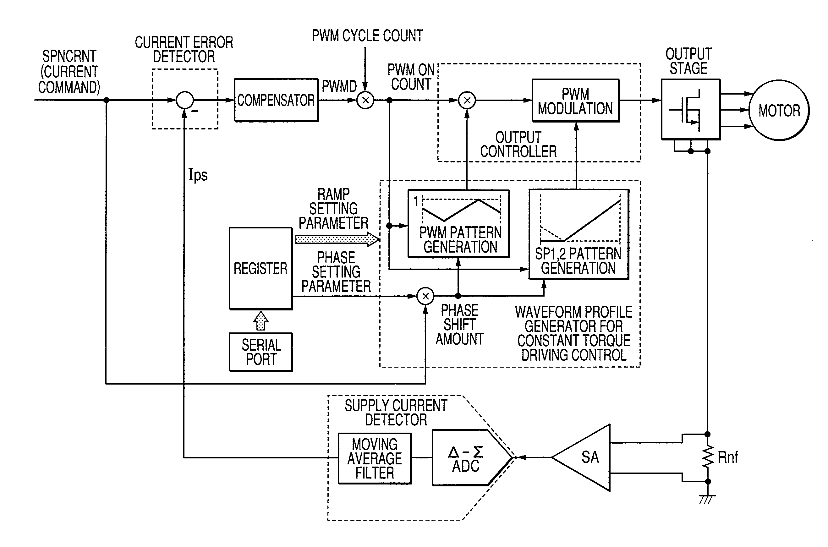
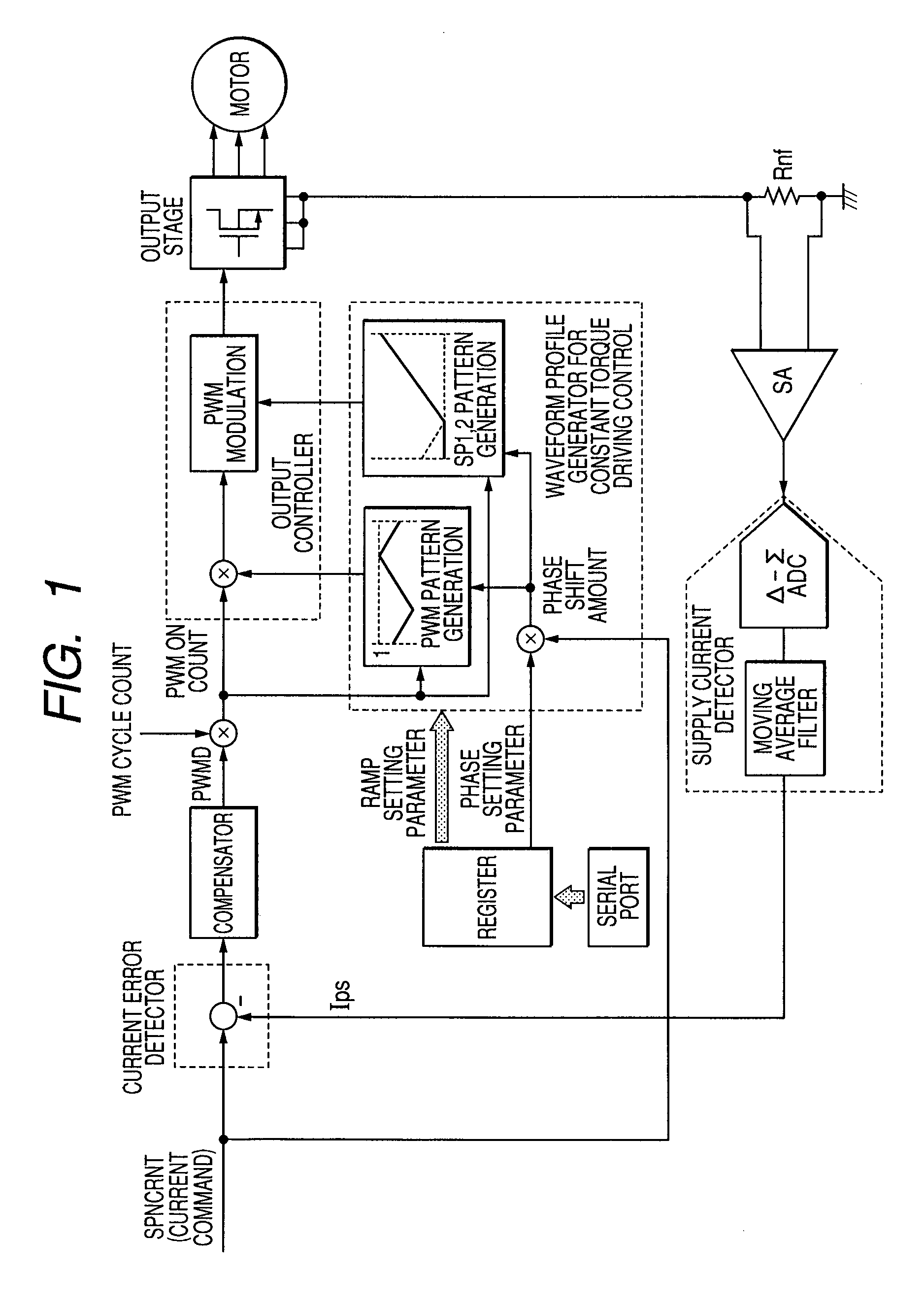
[0027]FIG. 1 shows a block diagram of a current control block that performs constant torque driving by 180 deg conduction in a motor driving apparatus according to the invention. To drive a three-phase DC motor with a proper torque, the current control block uses current values detected by a DC shunt resistor Rnf, controls the PWM duty so that the current value conforms to a current command, and outputs PWMCLK. The motor drive current detected by the DC shunt resistor Rnf is amplified by a sense amplifier SA and converted into a digital value at high speed by a digital / analog converter (hereinafter referred to as Δ-Σ ADC). The Δ-Σ ADC output passes through a moving average filter with a transmission zero set at a PWM frequency, whereby PWM frequency components are removed, and this output Ips is subjected to current error detection.

[0028]The output Ips of moving average filter is an average of the current flowing across the DC shunt resistor Rnf and, therefore, the detected current ...


PUM


Abstract

This invention provides a motor driving apparatus that made it possible to reduce torque ripples including those attributed to load variation of the motor and an associated method for control of motor revolution. An output stage to a multiphase DC motor is comprised of power elements to supply output voltages to multiphase coils and a predriver to supply drive voltages to the power elements. A resistor means detects a current flowing through the power elements. A supply current detector detects a voltage signal produced across the resistor means as a supply current, using a high-speed ADC and a moving average filter. An output controller generates a PWM signal with a frequency lower than the frequency of the high-speed ADC so that the current detected by the supply current detector conforms to a current signal indicating a motor revolving speed and transfers the PWM signal to the output stage.

Description

CROSS-REFERENCE TO RELATED APPLICATIONS[0001]The disclosure of Japanese Patent Application No. 2007-216610 filed on Aug. 23, 2007 including the specification, drawings and abstract is incorporated herein by reference in its entirety.BACKGROUND OF THE INVENTION[0002]The present invention relates to a motor driving apparatus and a method for control of motor revolution and relates to a technique that is effectively used as a revolution control technique for a three-phase spindle motor of a hard disk drive (HDD), for example.[0003]For driving the spindle motor of an HDD system, a soft switching method is used in which PWM is performed for two phases during current-conducting phase switching to suppress a steep change in current. In order to rotate a motor, detecting the motor position is needed. As a sensor-less method, it is known that the back electromotive force (BEMF) of the motor is detected during a non-conducting period following the current-conducting phase switching. Detecting...

Claims


Application Information

Patent Timeline
Patent Type & Authority Applications(United States)
IPC IPC(8): H02P6/16H02P6/10H02P6/06H02P6/08H02P6/28
CPCG11B19/28H02P6/18H02P6/10
Inventor KUROSAWA, MINORUKOKAMI, YASUHIKO
Owner RENESAS ELECTRONICS CORP
Why Eureka
Try Eureka