
Internal shape of rotor for two-bore rotary carburetor used in stratified scavenging engine

Active Publication Date: 2009-03-19
ZAMA JAPAN
View PDF11 Cites 14 Cited by
  • Summary
  • Abstract
  • Description
  • Claims
  • Application Information

AI Technical Summary

Benefits of technology

[0007]An object of the present invention is to provide an internal shape of a rotor for a two-bore rotary carburetor used in a stratified scavenging engine whereby an engine for a power saw, lawn mower, or the like can be stabilized in the course of a complete change in orientation during idling.
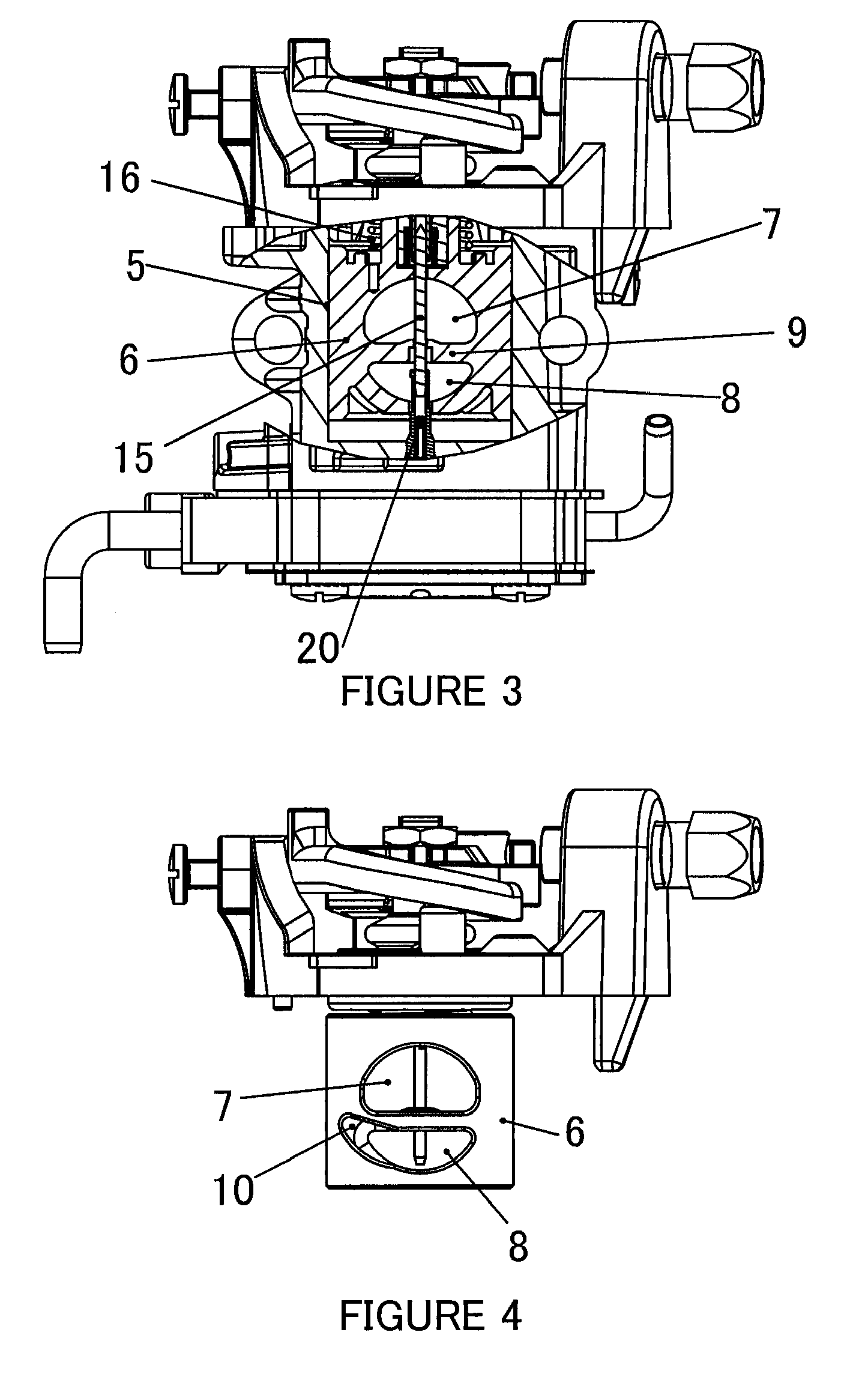
[0013]In a two-bore rotary carburetor used in a stratified scavenging engine according to the present invention, a minimal groove pocket is formed at the aperture edge of each of the downstream end and upstream end of the rotor valve on the side located in the accelerated rotation direction in the fuel supply-side bore. Therefore, operation at the groove pocket of the fuel supply-side bore can be carried out in the period from idling to the throttle opening maintained during idling, and all the air and fuel can be fed to the engine via the groove pocket. Accordingly, an emulsion can be formed relatively rapidly and fed to the engine, making it possible to reduce the drop in rotation in the course of a complete change in orientation during idling.
[0014]In a two-bore rotary carburetor used in a stratified scavenging engine according to the present invention, each of the groove pockets is formed at the aperture edge symmetrically relative to a center axis and has a shape that gradually rises and decreases in cross-sectional surface area toward an accelerated rotation direction along a peripheral surface of the rotor valve. Therefore, it is possible to reduce the variation in the amount of air when the air supply-side bore starts to open in the period from idling to a partial state, making it easier to control the air-fuel ratio at a partial throttle opening. (Variation in CO % can be minimized.)
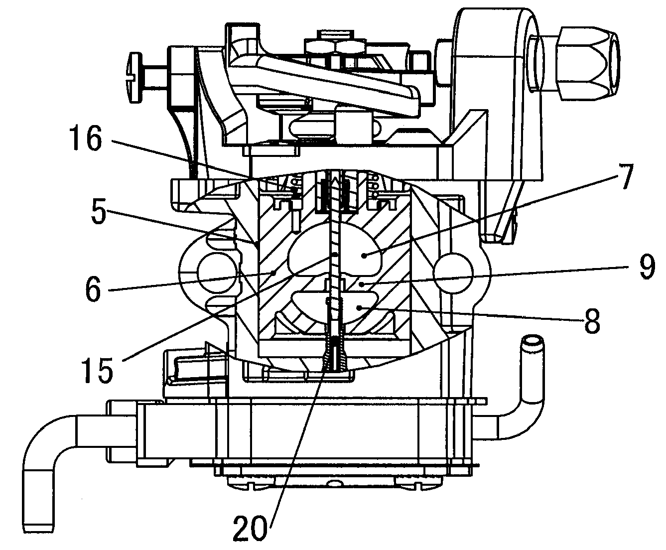
[0015]In a two-bore rotary carburetor used in a stratified scavenging engine according to the present invention, concavities of the groove pockets in the fuel supply-side bore are disposed toward the upstream and downstream sides of the nozzle part in the center, and the expansion and contraction of air during a fully opened state do not reach the nozzle part. Therefore, stability of the air-fuel ratio in a fully opened state is not compromised, and the fuel can be stably controlled.

Problems solved by technology

However, it is difficult to maintain a lean air-fuel ratio at idling by merely installing a partition in the same bore because the structural features of the rotor carburetor designed to aid in controlling the air-fuel ratio cause the rotor to be displaced downward at the throttle opening maintained during idling, and result in an arrangement in which the bore on the side of the air supply opens first, and the bore on the side of the fuel supply opens second.
The bore on the side of the fuel supply can be made to open first during idling if the shape of the bore on the side of the fuel supply is made symmetrically larger, but because the air-fuel ratio varies greatly when the bore on the side of the air supply starts to open in a partial state, it is difficult to control the fuel so that an optimal air-fuel ratio is obtained.

Method used


Image

  • Internal shape of rotor for two-bore rotary carburetor used in stratified scavenging engine
  • Internal shape of rotor for two-bore rotary carburetor used in stratified scavenging engine
  • Internal shape of rotor for two-bore rotary carburetor used in stratified scavenging engine

Examples


Embodiment Construction

[0031]An example of an internal shape of a rotor for a two-bore rotary carburetor used in a stratified scavenging engine according to the present invention is described below with reference to the accompanying drawings.

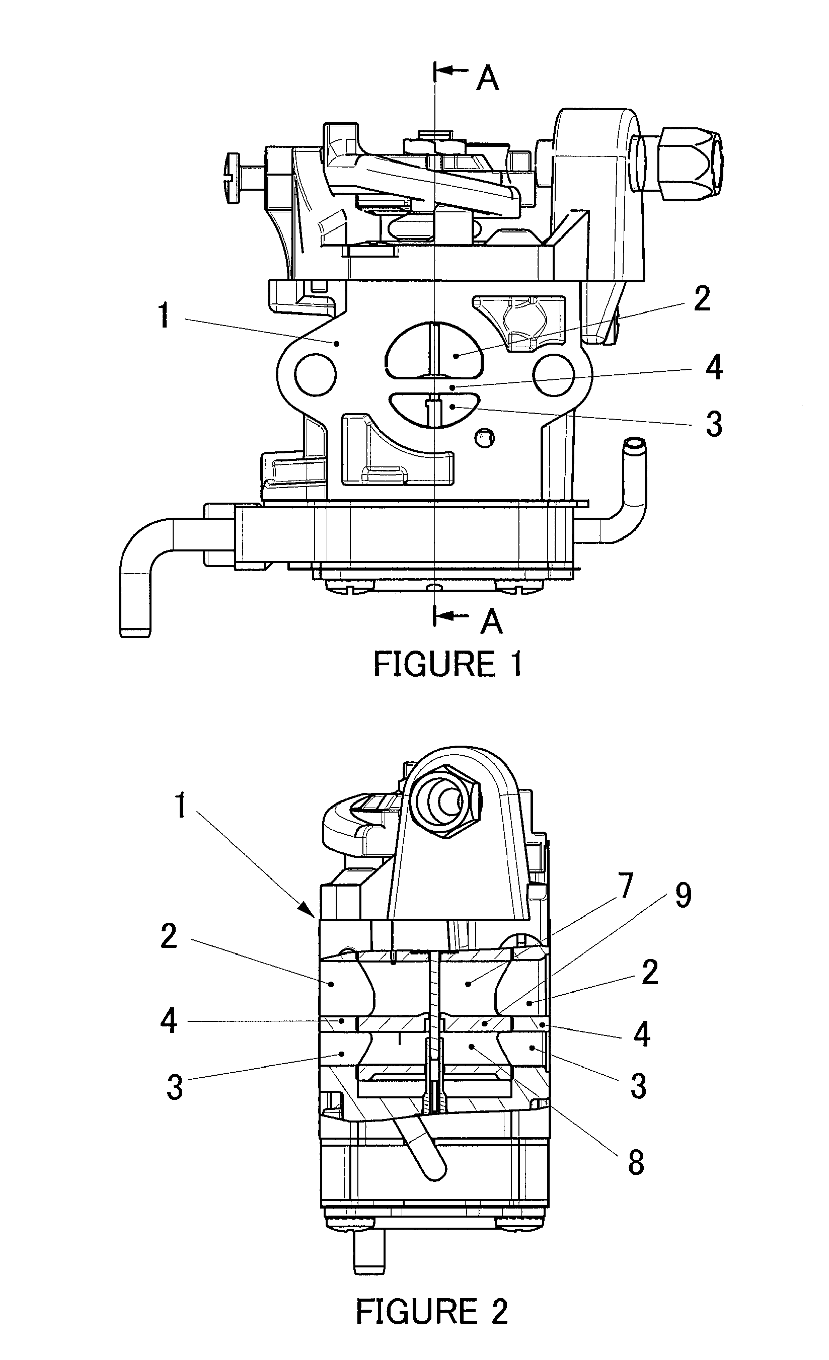
[0032]FIG. 1 is a front view of an example of a two-bore rotary carburetor for a stratified scavenging engine according to the present invention. In the drawing, 1 is the carburetor main body, 2 is an air channel formed through the carburetor main body 1, 3 is a mixing channel formed through the carburetor main body 1, and 4 is a partition formed in the carburetor main body 1 and used to separate the air channel 2 and the mixing channel 3.

[0033]As shown in FIG. 2, which is a cross section obtained by cutting FIG. 1 along line A-A, the mixing channel 3 is disposed underneath the air channel 2 in the carburetor main body 1; i.e., the channels are disposed one above the other so that when a the carburetor main body is cross-cut in a horizontal direction, the air channel ...


PUM

PropertyMeasurementUnit
Diameteraaaaaaaaaa
Surface areaaaaaaaaaaa

Abstract

The present invention provides an internal shape of a rotor for a two-bore rotary carburetor used in a stratified scavenging engine whereby an engine for a power saw, lawn mower, or the like can be stabilized in the course of a complete change in orientation during idling. A groove pocket (10) in communication with a fuel supply-side bore (8) is formed at the aperture edge of each of the upstream end and the downstream end of a carburetor rotor valve (6) toward an accelerated rotation direction in the fuel supply-side bore (8) of the rotor valve (6). The groove pocket (10) is shaped so as to gradually rise and decrease in cross-sectional surface area toward the accelerated rotation direction along a peripheral surface of the rotor valve (6). The resulting structure is one in which the groove pocket (10) is initially superposed with the mixing channel during horizontal rotation of the rotor valve (6), the fuel supply-side bore (8) and the mixing channel are in communication with each other, and the fuel supply-side bore (8) opens before the air supply-side bore (7) does.

Description

BACKGROUND OF THE INVENTION[0001]1. Field of the Invention[0002]The present invention relates to an internal shape of a rotor for a two-bore rotary carburetor used in a stratified scavenging engine applicable to a two-stroke internal combustion engine for a power saw, lawn mower, or the like.[0003]2. Description of the Related Art[0004]There are conventionally known carburetors for a two-cycle engine in which the terminal end of an air channel is connected to a portion adjacent to the scavenging port of a scavenging channel for connecting the scavenging port and the crankcase of the engine. The air channel is provided with a check valve for allowing air to flow to the scavenging channel. The starting end of the air channel is connected to the inlet portion of an air intake conduit. The air channel is provided with an air control valve for varying the amount of air; and the air control valve for varying the amount of air in the air channel is provided as an integrated structure toget...

Claims


Application Information

Patent Timeline
IPC IPC(8): F02M9/08
CPCF02B25/20F02M17/04F02M13/04F02M9/08Y10S261/01
Inventor KOIZUMI, KIMIO
Owner ZAMA JAPAN
Learn More