Method and system for drying casting molds
a mold and ceramic technology, applied in the field of casting methods, can solve the problems of significant contribution to time and cost of casting metal parts, negative impression of metal parts to be cast in molds, and labor-intensive and time-consuming process, so as to improve drying performance, and reduce mold drying time intervals
Active Publication Date: 2009-03-19
STURM RUGER & CO INC
View PDF30 Cites 7 Cited by
- Summary
- Abstract
- Description
- Claims
- Application Information
AI Technical Summary
Benefits of technology
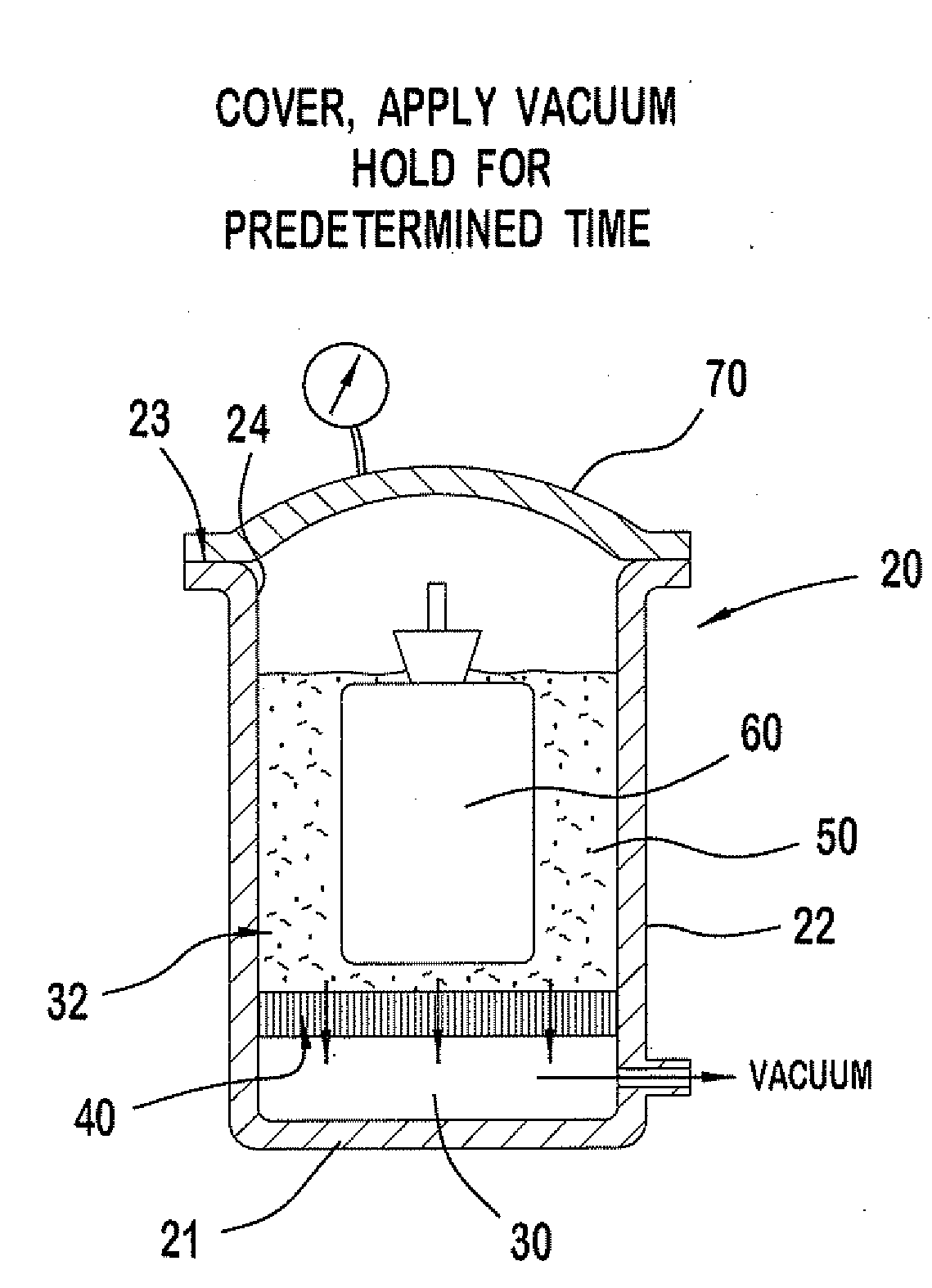
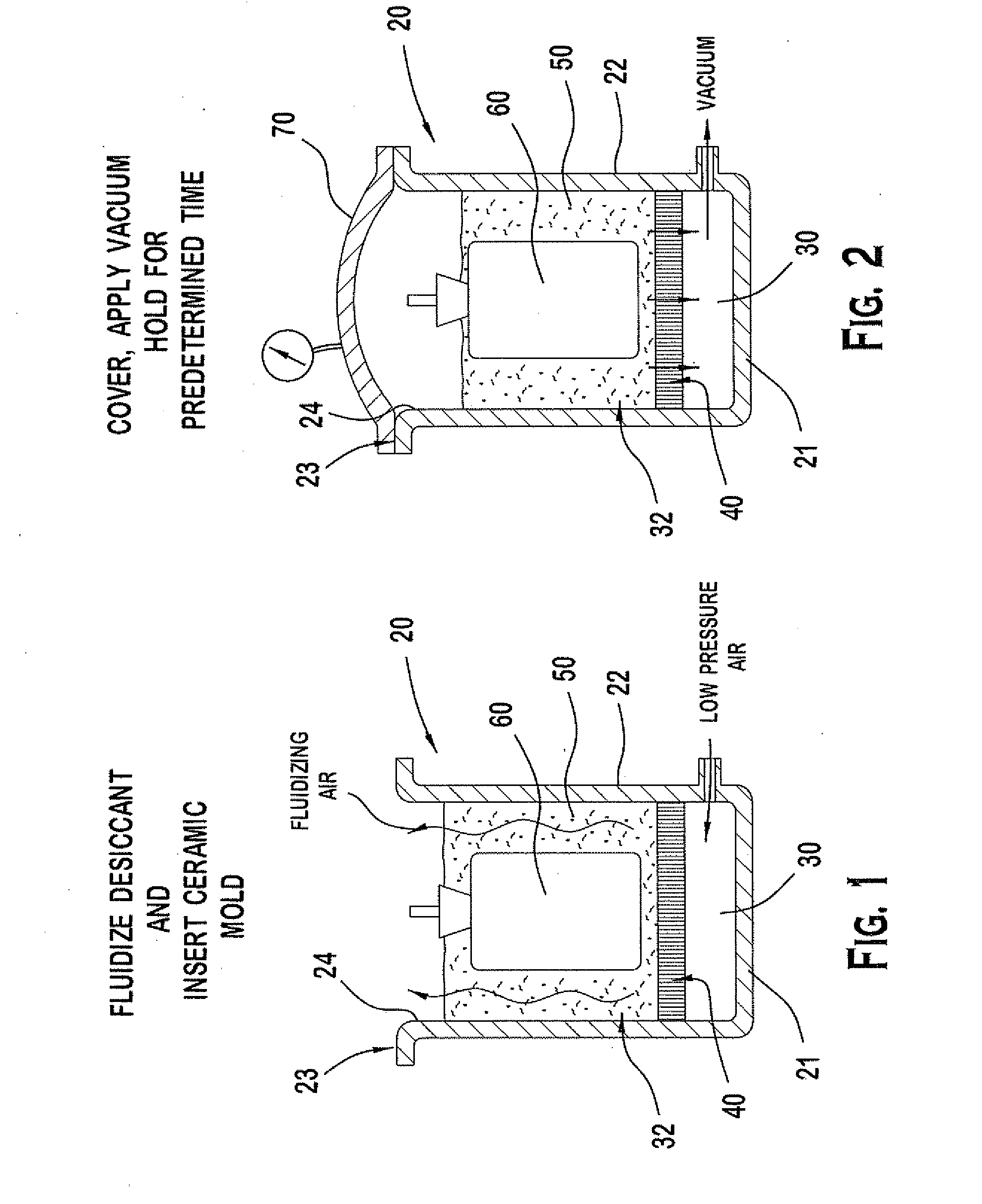
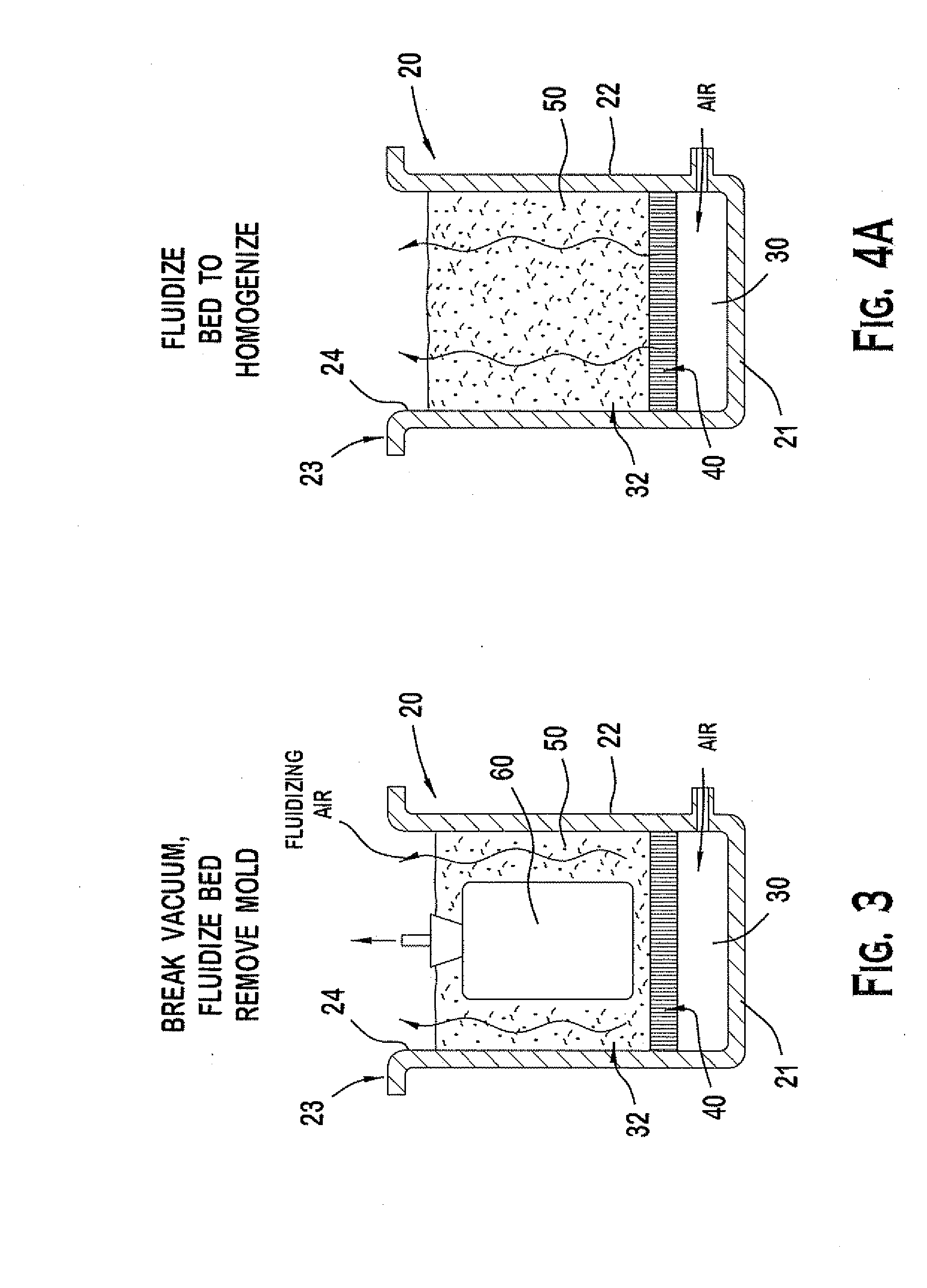
[0013]A system for and method of drying casting mold shells is provided that overcomes the drawbacks of known drying techniques described herein. In a preferred embodiment, the method includes using the combination of a vacuum and desiccant for improving drying performance while controlling the temperature change in the wax to within acceptable levels that avoid damaging the mold. Advantageously, the preferred vacuum-desiccant system and method reduces mold drying times while concomitantly balancing heat lost from the system through evaporative cooling of the mold in the vacuum with the heat liberated and gained from the desiccant during liquid removal from the mold without the need for usin
Problems solved by technology
Although a capital intensive and time-consuming process, investment casting employing the lost wax process permits high quality metal parts or components to be produced that include intricate details and configurations.
This leaves a negative impression of the metal part to be cast in the mold.
Because each shell layer must be thoroughly dried between each successive dipping into the ceramic slurry to at least gel the binder, the shell drying time between the multiple layers of ceramic shells significantly contributes to time and cost of producing the cast metal part.
More complex mold geometries and/or the presence of deep holes and slots, however, require longer drying times for the ceramic shells and adversely effect the ability to uniformly dry the shells.
It will be appreciated that these factors and poor airflow dynamics in drying rooms make it difficult to effectively control the drying rate and temperature of the ceramic shells, and to uniformly dry the molds.
High stresses can also create
Method used
View moreImage
Smart ImageViewing Examples
Examples
 PUM
| Property | Measurement | Unit |
|---|---|---|
| Fraction | aaaaa | aaaaa |
| Fraction | aaaaa | aaaaa |
| Fraction | aaaaa | aaaaa |
Abstract
A system and method of drying casting molds for forming metal parts is provided. In one embodiment, the method includes providing a casting mold comprised of a meltable pattern coated with a ceramic slurry containing a liquid solvent and a binder, placing the casting mold in a chamber, encapsulating the casting mold in a desiccant material, sealing the chamber sufficient to pull a vacuum in the chamber, and applying a variable vacuum to the chamber to dry the mold. In one embodiment, the vacuum is controlled and gradually increased over time from atmospheric pressure to a predetermined maximum vacuum pressure. The vacuum is preferably applied at a rate such that the meltable pattern has a temperature that does not decrease more than about 5 degrees F. from atmospheric pressure to maximum vacuum pressure in one embodiment. In another embodiment, the retained moisture level of the desiccant may be controlled to minimize temperature swings of the meltable pattern during the vacuum application.
Description
CROSS-REFERENCE TO RELATED APPLICATIONS[0001]This application claims the benefit of priority to U.S. Provisional Application No. 60 / 973,186 filed Sep. 18, 2007, which is incorporated herein by reference in its entirety.BACKGROUND OF THE INVENTION[0002]The present invention generally relates to casting methods, and more particularly to a method of drying ceramic molds such as those used in an investment casting process.[0003]Although a capital intensive and time-consuming process, investment casting employing the lost wax process permits high quality metal parts or components to be produced that include intricate details and configurations. Investment cast parts are used in the firearm, medical device, automotive, aerospace, manufacturing, power generation, oil and chemical, and other enumerable industries. Investment casting initially entails making meltable wax patterns of the metal parts desired to be manufactured by injecting wax in to a metal die. The individual wax patterns are...
Claims
Login to View More Application Information
Patent Timeline
 IPC IPC(8): B22C9/12
CPCB22C9/12
Inventor OLES, MARK
Owner STURM RUGER & CO INC
Features
- R&D
- Intellectual Property
- Life Sciences
- Materials
- Tech Scout
- Unparalleled Data Quality
- Higher Quality Content
- 60% Fewer Hallucinations
Learn More Browse by: Latest US Patents, China's latest patents, Technical Efficacy Thesaurus, Application Domain, Technology Topic, Popular Technical Reports.
© 2025 PatSnap. All rights reserved.Legal|Privacy policy|Modern Slavery Act Transparency Statement|Sitemap|About US| Contact US: help@patsnap.com


