
Unmanned helicopter

Inactive Publication Date: 2009-03-12
YAMAHA MOTOR CO LTD
View PDF1 Cites 43 Cited by
  • Summary
  • Abstract
  • Description
  • Claims
  • Application Information

AI Technical Summary

Benefits of technology

[0021]In view of the circumstances noted above, an aspect of the least one of the embodiments disclosed herein is to assist the GPS sensors for performing a program flight by autonomous control, in an unstable characteristic accompanying the usage thereof. Specifically, an object of the present invention is to provide a system that can detect a current location of the unmanned helicopter and thereby perform a program flight by autonomous control even if the number of GPS satellites from which the system receives signals (which can be radio waves) is less than a desired number of satellites, or even if data communication is interrupted.
[0022]In accordance with one aspect of the invention, an unmanned helicopter is provided. The unmanned helicopter comprises an airframe with a plurality of GPS antennas disposed thereon, the GPS antennas configured to receive a signal from at least one GPS satellite. The unmanned helicopter also comprises an autonomous controller configured to control the helicopter based at least in part on airframe data and flight route data and to communicate with a ground station, the controller comprising a plurality of GPS receivers, each receiver corresponding to one of the plurality of GPS antennas and defining therewith a GPS device configured to detect a location of the airframe, the GPS devices being different from each other.
[0021]In view of the circumstances noted above, an aspect of the least one of the embodiments disclosed herein is to assist the GPS sensors for performing a program flight by autonomous control, in an unstable characteristic accompanying the usage thereof. Specifically, an object of the present invention is to provide a system that can detect a current location of the unmanned helicopter and thereby perform a program flight by autonomous control even if the number of GPS satellites from which the system receives signals (which can be radio waves) is less than a desired number of satellites, or even if data communication is interrupted.
[0021]In view of the circumstances noted above, an aspect of the least one of the embodiments disclosed herein is to assist the GPS sensors for performing a program flight by autonomous control, in an unstable characteristic accompanying the usage thereof. Specifically, an object of the present invention is to provide a system that can detect a current location of the unmanned helicopter and thereby perform a program flight by autonomous control even if the number of GPS satellites from which the system receives signals (which can be radio waves) is less than a desired number of satellites, or even if data communication is interrupted.
[0021]In view of the circumstances noted above, an aspect of the least one of the embodiments disclosed herein is to assist the GPS sensors for performing a program flight by autonomous control, in an unstable characteristic accompanying the usage thereof. Specifically, an object of the present invention is to provide a system that can detect a current location of the unmanned helicopter and thereby perform a program flight by autonomous control even if the number of GPS satellites from which the system receives signals (which can be radio waves) is less than a desired number of satellites, or even if data communication is interrupted.
[0063]A distance K between antennas (refer to FIG. 6) is set to a length between one wavelength and two wavelengths of a GPS radio wave in order to reduce an influence of a reflected wave caused by each GPS antenna. Specifically, since one wavelength of the GPS radio wave is about 20 cm (precisely, λ=19 cm), the distance K can be set to about 30 cm, which is between one wavelength, 20 cm, and two wavelengths, 40 cm.

Problems solved by technology

Characteristically, an attitude of the airframe of the unmanned helicopter is easily disturbed by wind or the like.
Further, structural features of the unmanned helicopter can result in extreme changes in attitude during a flight while a turn is made.
Further, if the unmanned helicopter of such a type is, for example, caught by a strong crosswind, the flight route may extremely deviate from an intended flight route.
Accordingly, there may be a case in which autonomous control takes a long time to correct a flight route.
Accordingly, if there is a metal object, a building, a mountain, a machine, a man, a bird, or the like in a space between the satellite and a GPS antenna provided on the unmanned helicopter, the accuracy of a sensed location of the helicopter may be deteriorated, or a radio wave may not be received.
In addition, since the GPS satellites are managed by the United States Department of Defense, usage thereof may be restricted in a case of a national emergency.
The positioning accuracy of the GPS receiver, however, includes an error of about 15 m to 100 m because the positioning accuracy depends on a reception accuracy of a radio wave from the satellites.
Therefore, an operation thereof is not always secure.
An operation may be disabled because of an environment or a situation such as an interruption of a satellite radio wave by an obstacle or the like.
An operation of such a GPS device is disabled problematically if the number of GPS satellites from which a radio wave is received is less than a necessary number or if data from the standard station is not received.
Such an unmanned helicopter provided with such an automatic return program, however, causes a problem when the helicopter cannot receive radio waves from GPS satellites.
Specifically, because the RTK-GPS positioning system is not sufficient for detecting a current location necessary for performing autonomous control, the automatic return program cannot function.

Method used


Image

  • Unmanned helicopter
  • Unmanned helicopter
  • Unmanned helicopter

Examples


Embodiment Construction

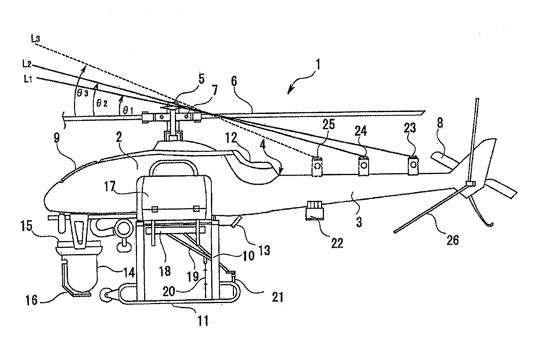
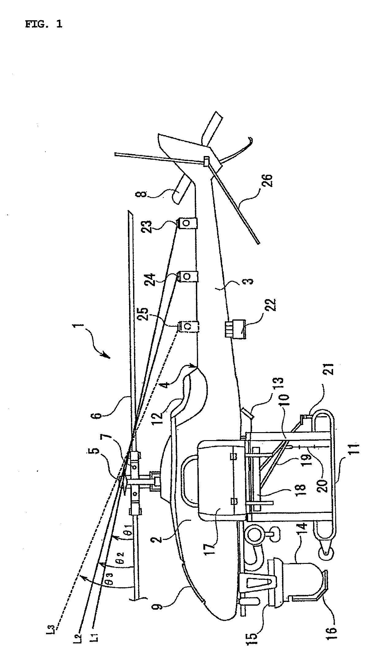
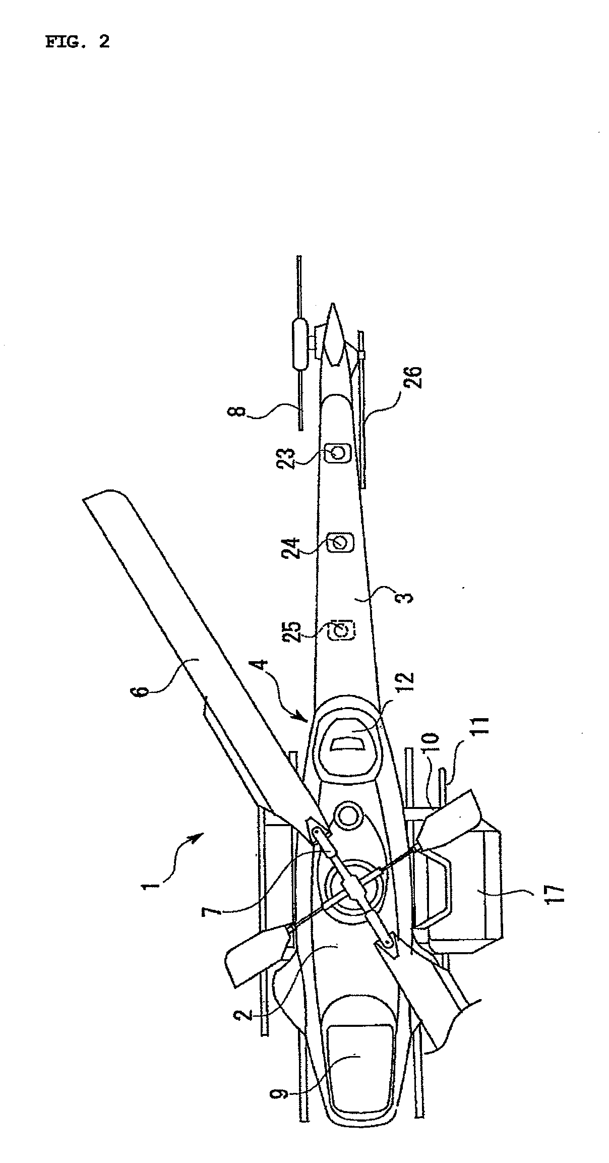
[0034]A helicopter 1 has an airframe 4 including a main body 2 and a tail body 3.

[0035]A main shaft 5 which rotates with a torque from an engine (not shown) is provided in the upper part of the main body 2. A main rotor 6 is connected with the main shaft 5 through a rotor support section 7. A tail rotor 8 is provided to the rear part of the tail body 3. A radiator 9 is provided to the front part of the main body 2. A skid 11 is provided via a support leg 10 at the left and the right sides and generally in the center part of the airframe 4 under the main body 2.

[0036]A control panel 12 is provided on the upper side of the rear part of the main body 2, while an indicating lamp 13 is provided on the lower side thereof. The control panel 12 displays a checkpoint, self diagnosis result and the like before a flight. A display on the control panel 12 can be confirmed also at a ground station. The indicating lamp 13 displays a state of a GPS control (the type of a GPS device currently in us...


PUM


Abstract

GPS devices (GPS receivers and corresponding GPS antennas) for detecting a location of an airframe are provided. An autonomous control section (e.g., an autonomous control box) including a data communication device for communicating with the ground and a control board having a built-in control program is provided. An unmanned helicopter flies depending on airframe data such as an attitude and a speed of the airframe, engine speed, and a throttle angle and flight data such as a location and a direction of the airframe. The autonomous control section is provided with a plurality of different type of GPS devices.

Description

CROSS-REFERENCE TO RELATED APPLICATIONS[0001]This application is a U.S. National Phase of the International Application No. PCT / JP2006 / 306327 filed Mar. 28, 2006 designating the U.S. and published in Japanese on May 10, 2006 as WO 2006 / 104158, which claims priority of Japanese Patent Application No. 2005-091914, filed Mar. 28, 2005.BACKGROUND OF THE INVENTION[0002]1. Field of the Invention[0003]The present invention relates to an unmanned helicopter for performing a program flight by autonomous control, and more particularly to Global Positioning System (GPS) sensor for detecting a location of the unmanned helicopter and to a method of using the same.[0004]2. Description of the Related Art[0005]Conventionally, a movie camera or a still camera mounted on a helicopter is used for photographing a view from the sky. In recent years in particular, such cameras have been mounted on an unmanned helicopter (as described in Japanese Publication JP 2002-166893, for example) that flies by remo...

Claims


Application Information

Patent Timeline
IPC IPC(8): G05D1/00
CPCB64C39/024B64C2201/024B64D43/00B64C2201/146B64C2201/145G05D1/0094B64U2201/104B64U2201/20B64U10/17B64U20/87B64U10/10
Inventor NAKAMURA, KATSU
Owner YAMAHA MOTOR CO LTD
Learn More