
Apparatus and methods for optical stimulation of neural tissues

a neural tissue and optical stimulation technology, applied in the field of neural tissue stimulation, can solve the problems of poor spatial specificity, coagulation or ablation of the target tissue, easy electrical interference of the electrical stimulation, etc., and achieve the effect of minimal tissue damag

Inactive Publication Date: 2009-03-12
VANDERBILT UNIV
View PDF3 Cites 61 Cited by
  • Summary
  • Abstract
  • Description
  • Claims
  • Application Information

AI Technical Summary

Benefits of technology

[0014]The method according to the present invention has advantages over the existing optical neural stimulation methodology by: 1) increasing spatial resolution to only the area where exogenous chromophore is loaded or placed, 2) increasing the number of lasers and wavelengths available for optical stimulation by changing the absorption properties of the target tissue (thus allowing stimulation), 3) enhancing existing optimal wavelengths to decrease the amount of laser energy required for stimulation as well as possibly increasing the energy required for tissue damage by acting as a heat sync in the nerve, 4) allowing the possibility of non-invasive stimulation by coating / loading the target neurons prior to stimulation and the use of a laser with a wavelength that is both capable of penetrating soft tissue as well as being highly absorbed by the input chromophore.
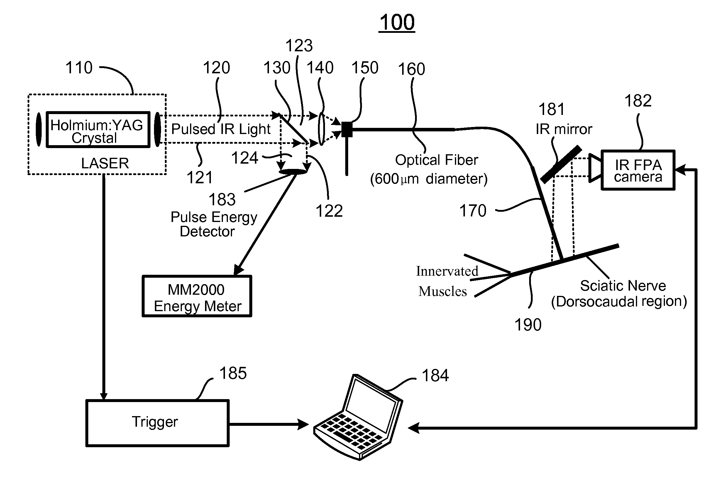
[0018]In one embodiment, the at least one beam of radiation has a wavelength selected such that when delivered to the target neural tissue, it causes a maximal temperature increase and a minimal tissue damage in the target neural tissue.
[0021]The beam of radiation has a wavelength selected such that when delivered to the target neural tissue, it causes a maximal temperature increase and a minimal tissue damage in the target neural tissue.

Problems solved by technology

However, electrical stimulation is prone to electrical interference from the environment, high frequency artifacts associated with the electrical signal used, intrinsic damage caused by the electrodes used for stimulation themselves, population response due to the recruitment of multiple axons, which prevents simultaneous stimulation and recording of adjacent areas, and in general poor spatial specificity.
Photothermal effects result from the transformation of absorbed light energy to heat, which may lead to hyperthermia, coagulation, or ablation of the target tissue [12].
These boundaries are not strict and adjacent interaction types cannot always be separated.
Therefore, a heretofore unaddressed need exists in the art to address the aforementioned deficiencies and inadequacies.

Method used


Image

  • Apparatus and methods for optical stimulation of neural tissues
  • Apparatus and methods for optical stimulation of neural tissues
  • Apparatus and methods for optical stimulation of neural tissues

Examples


Embodiment Construction

[0041]The present invention is more particularly described in the following examples that are intended as illustrative only since numerous modifications and variations therein will be apparent to those skilled in the art. Various embodiments of the invention are now described in detail. Referring to the drawings, like numbers indicate like components throughout the views. As used in the description herein and throughout the claims that follow, the meaning of “a”, “an”, and “the” includes plural reference unless the context clearly dictates otherwise. Also, as used in the description herein and throughout the claims that follow, the meaning of “in” includes “in” and “on” unless the context clearly dictates otherwise. Moreover, titles or subtitles may be used in the specification for the convenience of a reader, which shall have no influence on the scope of the present invention. Additionally, some terms used in this specification are more specifically defined below.

Definitions

[0042]T...


PUM


Abstract

The present invention, in one aspect, relates to a method for stimulating neural tissue of a living subject. In one embodiment, the method has the steps of generating at least one beam of radiation; introducing at least one of one or more chromophores and one or more optical agents to a target neural tissue; and delivering the at least one beam of radiation to the target neural tissue, wherein the at least one beam of radiation is delivered with a radiant exposure that causes a thermal gradient in the target neural tissue, thereby stimulating the target neural tissue.

Description

CROSS-REFERENCE TO RELATED PATENT APPLICATION[0001]This application claims the benefit, pursuant to 35 U.S.C. § 19(e), of U.S. provisional patent application Ser. No. 60 / 861,673, filed Nov. 27, 2006, entitled “APPARATUS AND METHODS FOR OPTICAL STIMULATION OF NEURAL TISSUES,” by Anita Mahadevan-Jansen, Jonathon D. Wells and E. Duco Jansen, which is incorporated herein by reference in its entirety.[0002]Some references, which may include patents, patent applications and various publications, are cited in a reference list and discussed in the description of this invention. The citation and / or discussion of such references is provided merely to clarify the description of the present invention and is not an admission that any such reference is “prior art” to the invention described herein. All references cited and discussed in this specification are incorporated herein by reference in their entireties and to the same extent as if each reference was individually incorporated by reference....

Claims


Application Information

Patent Timeline
IPC IPC(8): A61N5/067
CPCA61N5/0622A61N5/0618
Inventor MAHADEVAN-JANSEN, ANITAWELLS, JONATHON D.JANSEN, E. DUCO
Owner VANDERBILT UNIV
Learn More