
Methods and apparatuses for encoding and decoding an image

a technology of encoding and decoding images, applied in electrical devices, instruments, computing, etc., can solve problems such as difficult line structure and not the best possible line structur

Active Publication Date: 2009-03-12
NOKIA TECHNOLOGLES OY
View PDF16 Cites 36 Cited by
  • Summary
  • Abstract
  • Description
  • Claims
  • Application Information

AI Technical Summary

Benefits of technology

The present invention provides an apparatus and method for encoding and decoding an image by dividing the image into blocks and processing the pixels of each block separately. The size of each block can be different and the blocks can have different numbers of rows and columns. This allows for more efficient processing and synchronization points in the image. The invention also provides a bit stream comprising encoded pixels of an image, which can be used for wireless communication. The technical effects of the invention include improved image processing efficiency and better synchronization points for video and image processing.

Problems solved by technology

It is also possible that the image needs to be processed as blocks and so the line structure is not the best possible.
Line structure can also be difficult if the image needs to be rotated (or cropped) before the image processing.

Method used


Image

  • Methods and apparatuses for encoding and decoding an image
  • Methods and apparatuses for encoding and decoding an image
  • Methods and apparatuses for encoding and decoding an image

Examples


example 1

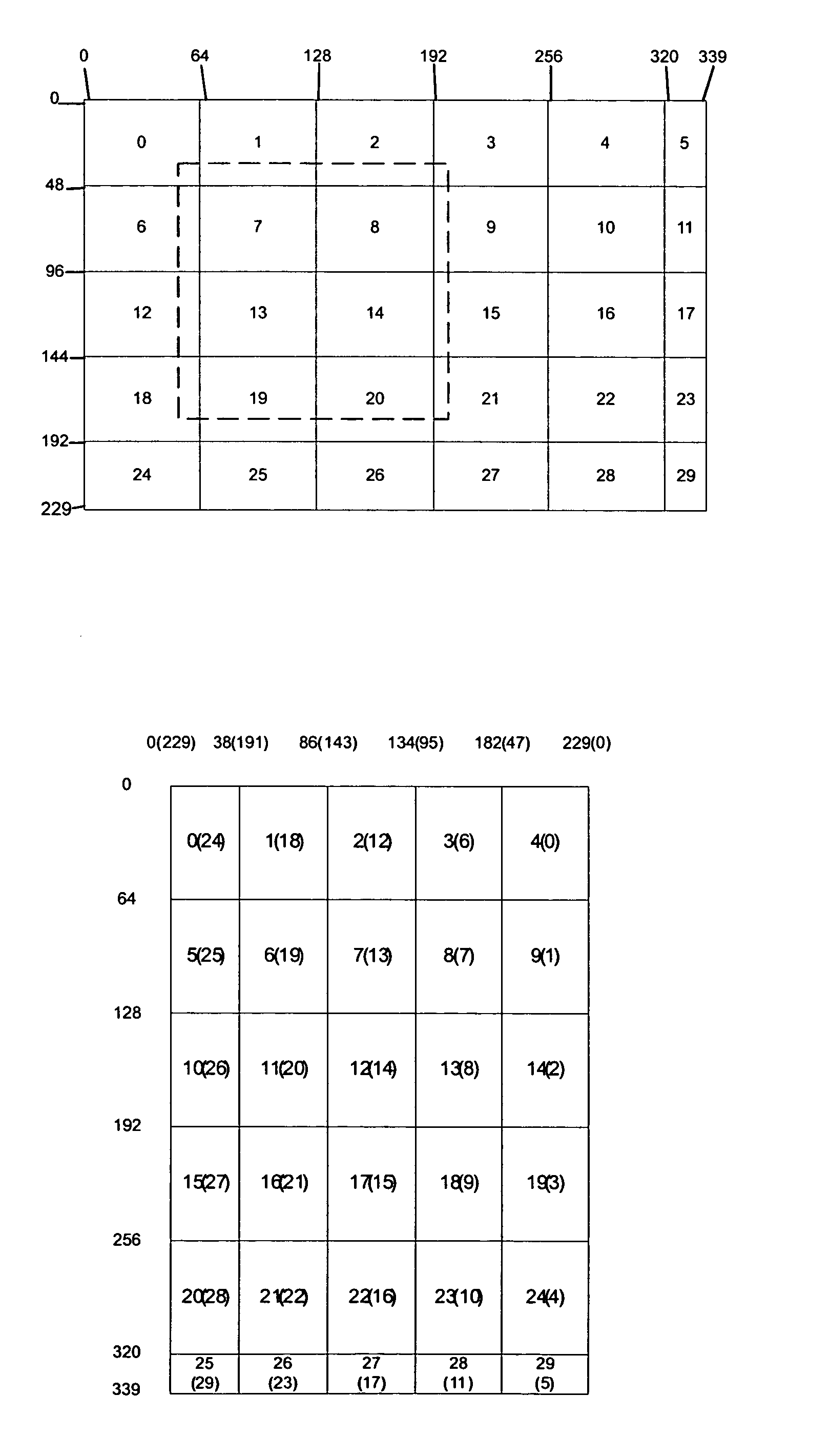
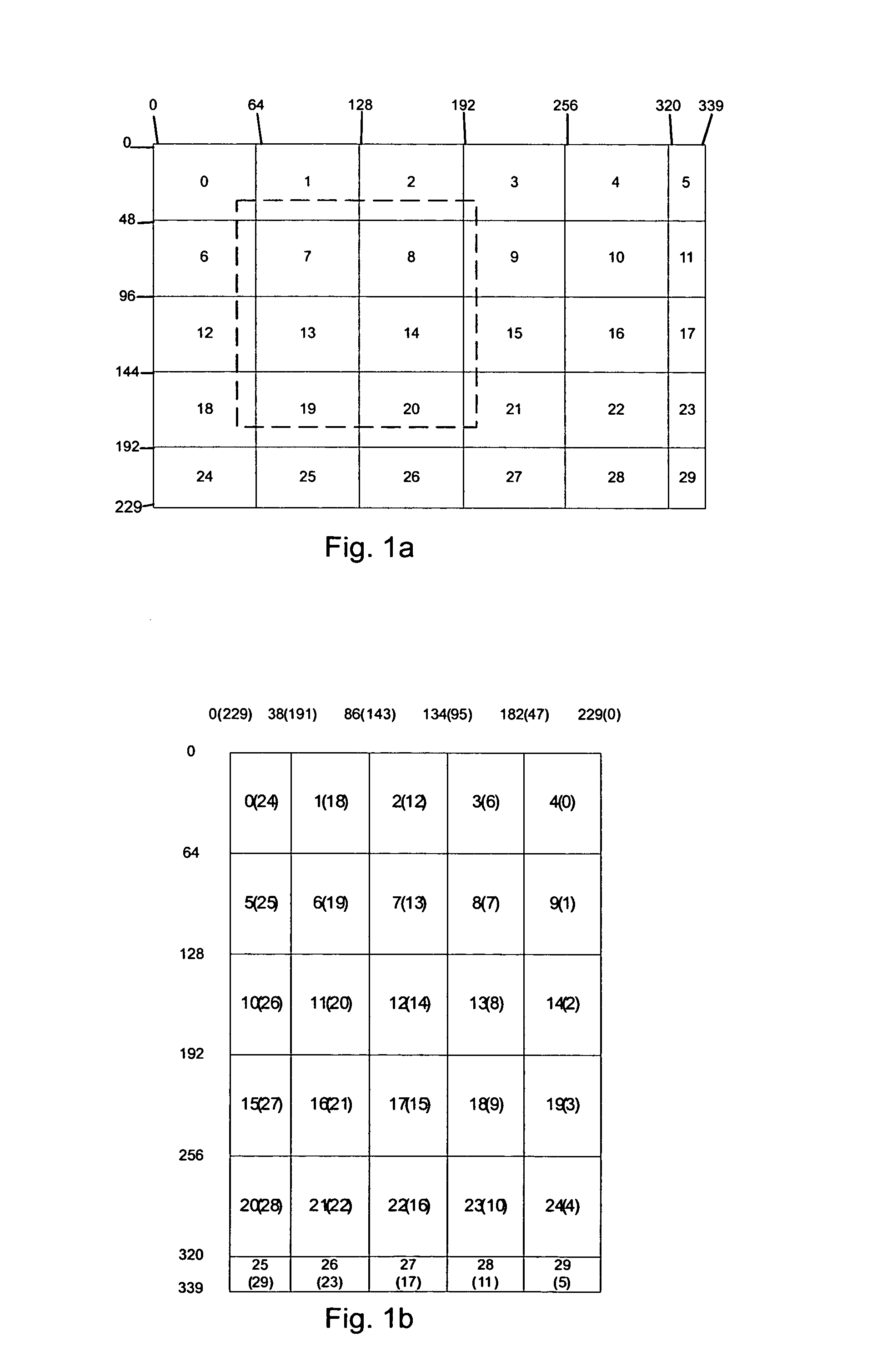
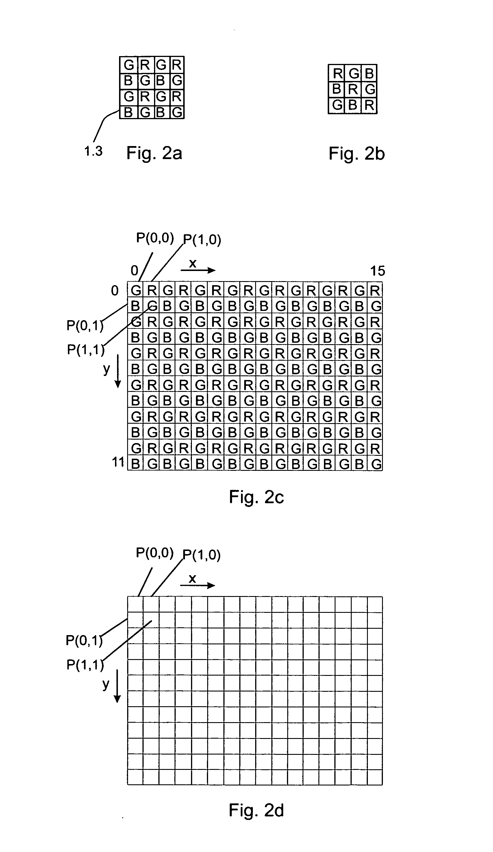
[0100]Next, the encoding of the image in an encoding apparatus 10 of FIG. 3c will be disclosed using the Bayer image format shown in FIGS. 2a and 2c as an example of the filter array. In FIG. 4 the encoding method according to an example embodiment is depicted as a flow diagram. It is assumed that the original pixel values are 10 bits width and the purpose of the encoding is to reduce the bit width to 8 bits. However, these values are just non-limiting examples and also other values can be used instead (from 10 bits to 7 bits, from 12 bits to 8 bits, from 16 bits to 12 bits, etc.). In FIG. 2c pixels of one block of the image are shown. In the non-limiting example of FIG. 2c, the block has 12 rows and 16 columns. Letters R represent red pixels, letters G represent green pixels, and letters B represent blue pixels. For clarity, FIG. 2d shows the block of FIG. 2c without the letters R, G and B. For encoding the blocks of the image one or more synchronizing points (synchronizing pixels)...

example 2

[0116]In the second example embodiment a synchronization value is selected for each row of each block of the image. Hence, the first two pixel values of each row are used as synchronization values and the other pixels of the same row are predicted using the previous pixel values of the same row. Thus, the second predictor 17 (i.e. for the prediction in the vertical direction) is not needed. Otherwise the operation follows the principles presented above.

[0117]The decision whether to use only one starting point for each block or to use one starting point for each row of each block may be based on the features of these alternatives. If one starting point is used the encoding / decoding efficiency can be increased compared to the usage of multiple starting points, but if multiple starting points are used the robustness of the encoding / decoding apparatus can be increased compared to the usage of one starting point only.

[0118]In the above it was assumed that the first predictor 11 and the s...


PUM


Abstract

A method as well as a system, a device, an encoding apparatus, a decoding apparatus, a module and a computer software product for image processing is disclosed. The image comprises a pixel matrix, in which the pixels comprise a first number of bits. The pixel matrix is divided to two or more blocks of pixels. The pixels are processed on a block-by-block basis to form encoded pixel values including a certain second number of bits. Bit strings are formed on the basis of the encoded pixels. When decoding the image the bit strings are examined to find out the encoding method used in encoding the pixel, and decoding is performed on a block-by-block basis to retrieve pixel values of the image.

Description

CROSS-REFERENCE TO RELATED APPLICATIONS[0001]This application claims priority under 35 USC §119 to International Patent Application No. PCT / FI2007 / 050445 filed on Aug. 16, 2007.FIELD OF THE INVENTION[0002]The present invention relates to a method for encoding an image comprising an array of pixels. The invention also relates to an encoding apparatus for encoding an image comprising an array of pixels, and a method for decoding the encoded image and a decoding apparatus. The invention further relates to a module for encoding an image, a module for decoding an image, a camera and a device comprising the encoder, a device comprising the decoder and a device comprising the camera. The invention also relates to a computer readable medium storing a computer program for encoding an image, and a computer readable medium storing a computer program for decoding an image.BACKGROUND OF THE INVENTION[0003]Image information can be formed by e.g. cameras having image sensors, which comprise a plur...

Claims


Application Information

Patent Timeline
Patent Type & Authority Applications(United States)
IPC IPC(8): G06K9/36H04N19/593
CPCG06T9/004H04N19/105H04N19/46H04N19/90H04N19/186H04N19/182H04N19/12
Inventor KALEVO, OSSI
Owner NOKIA TECHNOLOGLES OY
Learn More