System for extended high frame rate imaging with limited-diffraction beams

a high frame rate, limited beam technology, applied in the field of multi-dimensional image production systems, can solve the problems of reducing computation efficiency, low signal-to-noise ratio (snr), and not aiming at increasing the frame rate of conventional b-mode images, and achieves high frame rate, high contrast, and high resolution.

Inactive Publication Date: 2009-03-12
TOLEDO THE UNIV OF
View PDF13 Cites 34 Cited by
  • Summary
  • Abstract
  • Description
  • Claims
  • Application Information

AI Technical Summary

Problems solved by technology

Although this method may maintain a high frame rate at a large field of view due to the divergence nature of spherical waves, it may lower signal-to-noise ratio (SNR) and reduce computation efficiency as compared with the high frame rate imaging method.
However, the previous studies are not aimed at increasing the frame rate of conventional B-mode images.
Apparently, the imaging process is slow.
This method requires multiple transmissions to cover the Fourier space of object function and thus is slow.
Unfortunately, this method also requires a large number of transmissions to construct a frame of image.
One drawback of synthetic aperture methods is that they suffer from low, transmission efficiency since only part of the aperture of a transducer is used.
Because a large amount of transmissions is required to construct an image, the image frame rate is low in addition to poor quality due to a low SNR.
Nonetheless, Fourier-based synthetic aperture imaging is used with catheter-based ultrasound probes where a complex method is difficult to implement due to the confined space of these probes.
Although the method mal get a high-resolution image beyond the focal distance and may, have applications in ophthalmology, and dermatology, it is not suitable for high frame rate imaging because mechanical scanning is usually very slow.
However, their method uses a time-domain approach and the complexity of an imaging system would be formidably high if it were applied to a 3D imaging at a rate of a few thousands volumes / s.

Method used


Image

  • System for extended high frame rate imaging with limited-diffraction beams
  • System for extended high frame rate imaging with limited-diffraction beams
  • System for extended high frame rate imaging with limited-diffraction beams

Examples


example a

Mathematical Examples

[0191]To verify the extended HFR imaging theory in ideal conditions, computer simulations were performed. For simplicity, only 2D imaging will be considered. The simulation algorithms are developed based on the impulse response methods.

[0192]In the simulations, a 128-element, 1D linear array transducer of 3.5 MHz center frequency and 58%-6 dB pulse-echo fractional bandwidth defined bus the square of the Blackman window function is assumed. A one-cycle sine wave pulse at the center frequency of the transducer is used to excite the transducer. The dimensions of the transducer are 0.32 mm (pitch), 8.6 mm (elevation width), and 40.96 mm (aperture length), respectively. The pitch is about ¾ of the center wavelength of the transducer. There is no elevation focus for the transducer.

[0193]Two objects are used in the simulations. One is based on the wire pattern of the ATS539 (ATS Laboratories, Inc.) multipurpose tissue-mimicking phantom (see imaging Area I and the posit...

examples b and c

In Vitro and In Vivo Examples

[0201]To test the extended HFR imaging theory in practical situations, both in vitro and in vivo experiments are carried out with a homemade high frame rate (HFR) imaging system.

[0202]Example System and Conditions

[0203]A HFR imaging system was designed and constricted in our lab and was used for all the experiments. Tins system has 128 independent, wideband (0.05 MHz-10 MHz) arbitrary waveform generators (power amplifiers), and each of them has a 40 MHz 12-bit D / A as its input and produces up to ±144V output at a 75Ω load. The system also has 128 independent receiving channels, and each has a low-noise time-gain-control (TGC) amplifier of up to 108 dB gain and 10 MHz bandwidth (0.25 MHz-10 MHz) Each channel also has a 12-bit A / D of 40 MHz sampling rate and an SDRAM of up to 512 MB for storing digitized echo signals. Data are transferred through a USB 2.0 (high-speed) link to a PC for image construction. The system operation is controlled by the PC using ...

example b

In Vitro Examples

[0205]In the in vitro experiments, the same array, transducer as in the simulations is used, except that the real transducer has a bandwidth of about 50%, instead of 58% of the center frequency. Other imaging parameters for the experiments are also the same as those in simulations. To show the line spread function of the imaging methods, a homemade wire phantom consisting of six nation wires (0.25 mm in diameter) in a line with an inter-wire spacing of 20 mm is used and images constructed with limited-diffraction array beam and steered plane wave transmissions are shown in FIGS. 7 and 8, respectively. (There is one more wire in the third row that is 20 mm away from the line.)

[0206]To show how image frame rate trades off with improved image quality, results for 1 (up to 5277 frames / s with a speed of sound of 1477.56 m / s, Panel (a)), 11 (up to 479 frames / s. Panel (b)), 19 (up to 278 frames / s, Panel (c)), and 91 (up to 58 frames / s, Panel (d)) transmissions are obtained...


PUM


Abstract

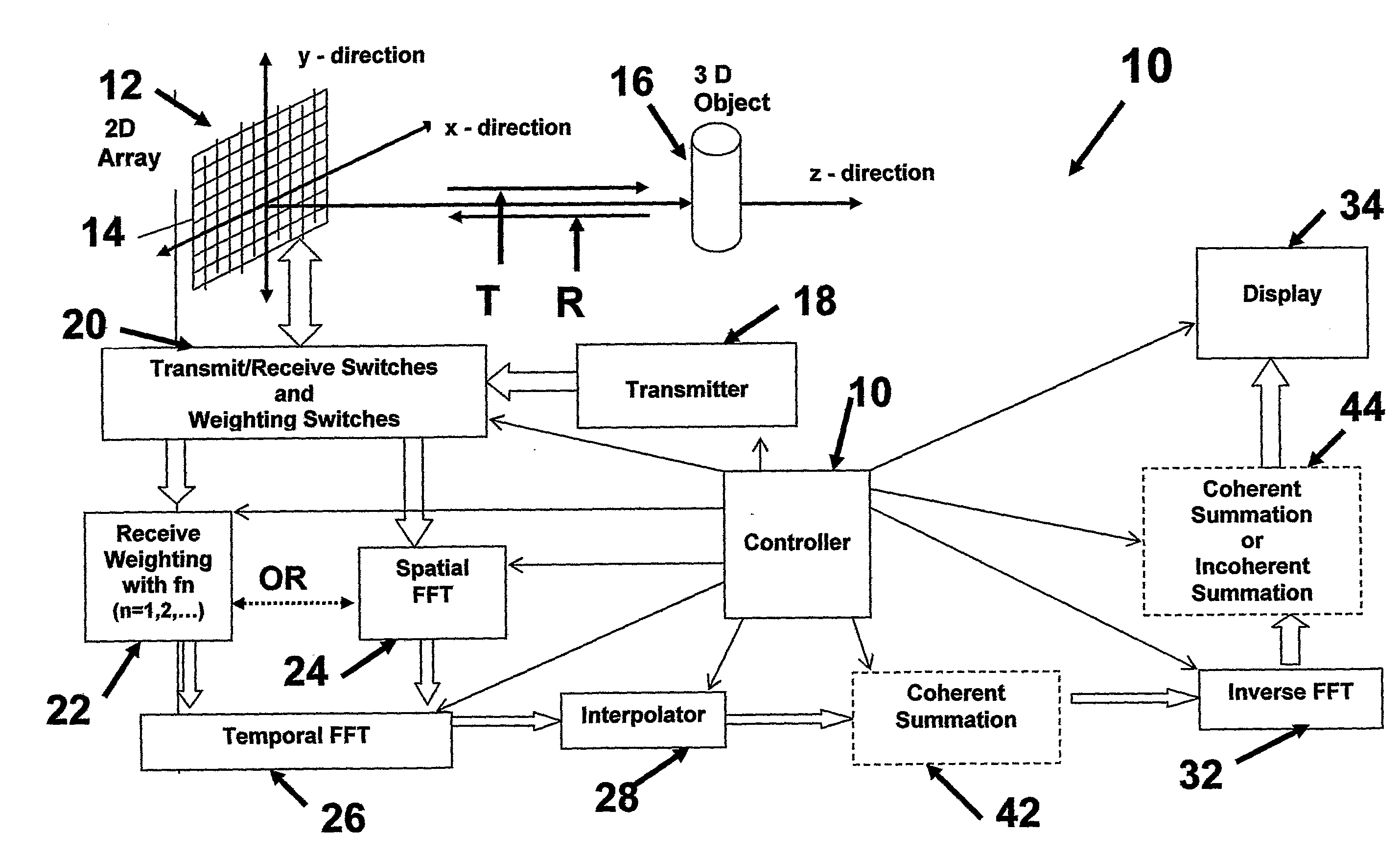
A system for producing a high frame rate image includes transmitting a single weighted spatial frequency signal of energy toward an object to be imaged; weighting multiple receive spatial frequency signals from the object, or by performing a spatial Fourier transform; reconstructing an image data set from the single transmitted spatial frequency signal and the multiple receive spatial frequency signals; and, reconstructing the high frame rate, high resolution and high contrast image from the image data set.

Description

RELATED APPLICATION[0001]This invention was made partly with government support under Contract No. HL60301 awarded by the National Institute of Health. The government has certain rights in this invention.FIELD OF THE INVENTION[0002]The present invention provides a method and a system for producing multi-dimensional images, including for example, two-dimensional: a single picture; three-dimensional: volumetric image; and four-dimensional: three-dimensional image sequence displayed over time.BACKGROUND OF THE INVENTION[0003]High frame rate imaging theorem uses a pulsed plane wave in transmission and limited-diffraction array beam weightings are applied to received echo signals to produce a spatial Fourier transform of object function for 3D image reconstruction.[0004]Because one transmission is used to construct an image, high image frame rate is achieved. In addition, because Fourier transform is implemented with a fast Fourier transform (FFT) which is a computationally efficient, si...

Claims


Application Information

Patent Timeline
Patent Type & Authority Applications(United States)
IPC IPC(8): G09G5/00
CPCG01S7/52046G01S15/8984G01S7/52085
Inventor LU, JIAN-YUCHENG, JIQI
Owner TOLEDO THE UNIV OF
Why Eureka
Try Eureka