
Liquid ejection head unit and image forming apparatus

a technology of liquid ejection and image forming apparatus, which is applied in the direction of printing, inking apparatus, other printing apparatus, etc., can solve the problems of wasteful method, difficulty in maintaining the nozzle in a normal state, and requiring time for users, and achieves the effect of simple configuration

Inactive Publication Date: 2009-03-05
RICOH KK
View PDF12 Cites 42 Cited by
  • Summary
  • Abstract
  • Description
  • Claims
  • Application Information

AI Technical Summary

Benefits of technology

[0024]The present invention has been made in view of the above problems and may detect the ejection of liquid droplets with a simple configuration without moving a head.
[0030]According to a liquid ejection head unit of the embodiments of the present invention, a liquid droplet detection unit has a light-emitting unit that emits light beams, a light-receiving unit that receives the light beams emitted from the light-emitting unit, and a light path forming unit that causes the light beams emitted from the light-emitting unit to pass through along a nozzle surface from the outer side of an area capped by a capping unit and that causes the light beams to be incident on the outer side of the area. Accordingly, it is possible to detect liquid droplets ejected from a head with a simple configuration without moving the head and interrupting the capping of the head.
[0031]With the provision of the liquid ejection head unit, the image forming apparatus of the embodiments of the present invention makes it possible to stably form high-quality images.

Problems solved by technology

Therefore, it is very difficult to maintain the nozzle in a normal state.
Therefore, it is a significant problem to maintain all the nozzles in a normal state, while avoiding ejection failures, such as a case in which the liquid droplets cannot be ejected from the nozzles, a case in which the liquid droplets are not ejected in the direction approximately perpendicular to a nozzle surface, and a case in which a desired size of the liquid droplets cannot be ejected.
However, this method wastefully consumes a sheet and requires time for the user to get accustomed to visually confirm the pattern.
On the other hand, according to the configuration described in Patent Document 5 that has the moving unit that makes it possible for the detector to be moved relative to the head unit, it is difficult to precisely move the detector.
In addition, if there is a failure in the moving unit of the detector, a target head unit cannot be detected.
Therefore, sufficient reliability is not obtained.
However, because the detector is provided for each nozzle, the interval between the detectors is small.
In addition, with the provision of many detectors, a wiring circuit becomes complicated.
Therefore, the costs of the head unit increase due to an ejection detecting mechanism.
Therefore, it is difficult to maintain the reliability of the detectors themselves.
Moreover, in the case of optical detection, heat is generated when light-emitting elements drive as the detectors, thereby causing the rise of the temperature of the head unit and the reduction of the sensitivity of light-receiving elements.
Accordingly, when the detectors are provided for the respective nozzles, a lot of heat is generated due to the accumulation of the light-emitting parts.

Method used


Image

  • Liquid ejection head unit and image forming apparatus
  • Liquid ejection head unit and image forming apparatus
  • Liquid ejection head unit and image forming apparatus

Examples


second embodiment

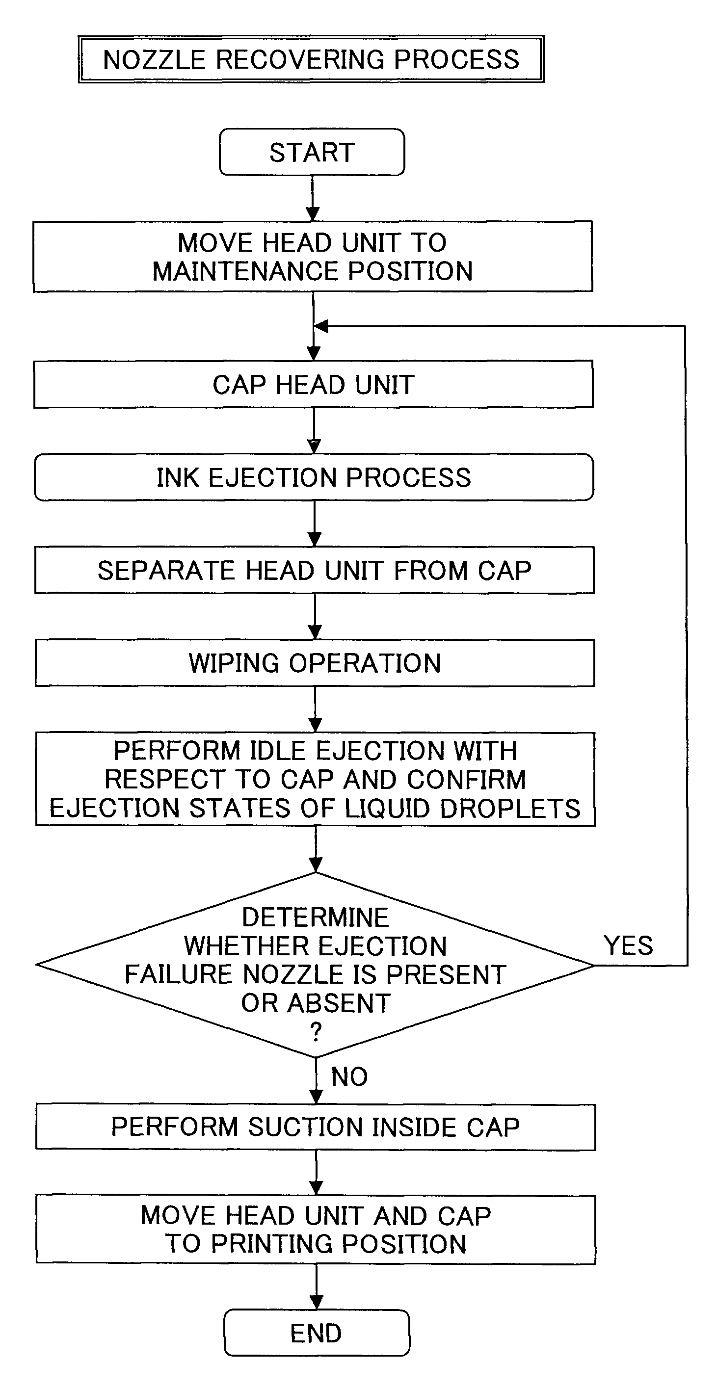
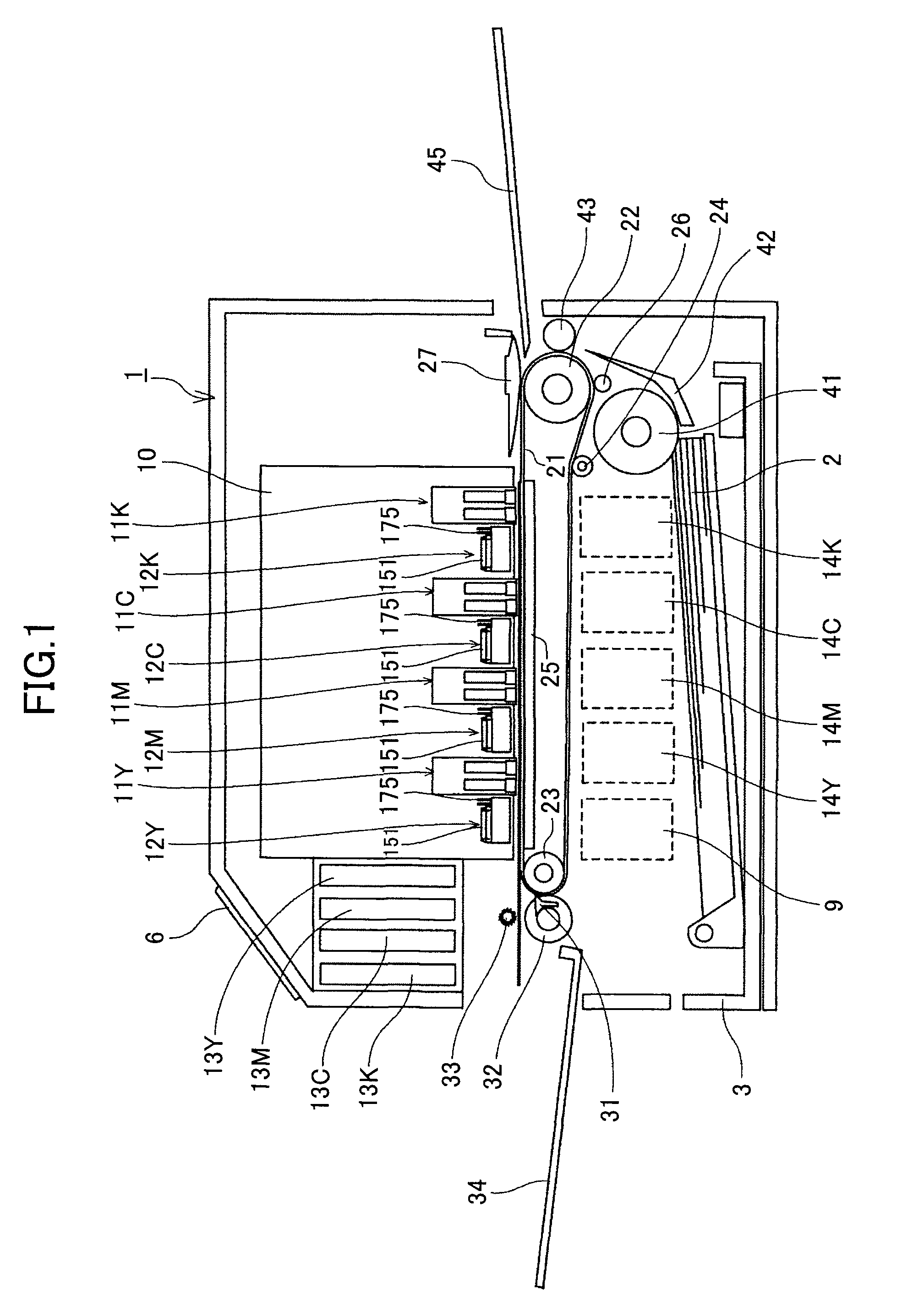
[0089]Furthermore, the head controlling unit 307 transfers instructions for detecting liquid droplets issued from the CPU 301 to a liquid droplet detection controlling unit 320. The liquid droplet detection controlling unit 320 controls a liquid droplet detection device 324 as a liquid droplet detection unit of the present invention described below in accordance with instructed timing. As described in detail below, the liquid droplet detection device 324 detects the ejection states of liquid droplets from the respective liquid ejection heads 101 of the head unit 11 via a light-emitting unit 325, a light-receiving unit 326, and a light axis deflecting unit 327 (in the case of the head unit described below) and transfers detection data obtained based on detection results to the CPU 301 via the liquid droplet detection controlling unit 320.

[0090]As the liquid ejection head for use in the image forming apparatus to which the present invention is applied, there can be employed, for examp...

first embodiment

[0130]Next, referring to FIGS. 15 through 20, a description is made of the liquid ejection head unit according to the present invention in the ink jet recording apparatus described above. Note that FIG. 15 is a perspective view of the head unit 11 and the maintenance unit, FIG. 16 is a perspective view of the head unit, FIG. 17 is an illustration for explaining light paths of the liquid droplet detection device in the head unit, FIG. 18 is an illustration for explaining a relationship between a light path direction of the liquid droplet detection device and a wiping direction, FIG. 19 is an illustration for explaining the dimensions of respective parts in the head unit, and FIG. 20 is an illustration for explaining a relationship between a detection light beam of the liquid droplet detection device and a nozzle.

[0131]As described above, the head unit 11 has the plural liquid ejection heads 101 supported on the head supporting member 100. In addition, the head unit 11 has the liquid ...

third embodiment

[0203]Next, referring to FIG. 34, a description is made of the liquid ejection head unit according to the present invention. Note that FIG. 34 is a perspective view of the head unit and the maintenance unit.

[0204]The head unit 11 has movable protection caps 230 as protection members that cover and protect the light-emitting mirror 155 and the light-receiving mirror 156 as the optical parts according to the first embodiment. Other configurations of the head unit 11 of this embodiment are the same as those of the head unit of the first embodiment.

[0205]Thus, the protection caps 230, which protect the optical parts (light-emitting mirror 155 and the light-receiving mirror 156) projecting on the head surface 100A of the head unit 11, are provided with cap-nipping parts 231 made of an elastic member so as to prevent the penetration of ink into the protection caps 230 and alleviate an impact generated when the protection caps 230 come into contact with the light-emitting mirror 155 and th...


PUM


Abstract

A liquid ejection head unit has plural liquid ejection heads and a liquid droplet detection device that detects liquid droplets ejected from the heads. The liquid droplet detection device has LD arrays that are provided at one side surface in the longitudinal direction of the head unit and serve to emit light beams; photo diodes that are provided at the other side surface in the longitudinal direction of the head unit and serve to receive the light beams emitted from the LD arrays; and a light path forming unit that causes the light beams emitted from the LD arrays to pass through along a head surface as detection light beams from the outer side of an area capped by a cap of a maintenance and recovery mechanism of an image forming apparatus and that causes the emitted light beams to be incident on the light-receiving unit provided at the outer side of the area.

Description

BACKGROUND OF THE INVENTION[0001]1. Field of the Invention[0002]The present invention generally relates to liquid ejection head units and image forming apparatuses and, in particular, to a liquid ejection head unit and an image forming apparatus capable of detecting liquid droplets ejected from a liquid ejection head.[0003]2. Description of the Related Art[0004]General image forming apparatuses, such as printers, facsimile machines, copiers, plotters, or multi-task machines having plural functions thereof, include a recording head composed of liquid ejection heads that eject liquid droplets of ink so as to form images. During image formation (used synonymously with recording, printing, and imaging), the image forming apparatuses cause the liquid droplets of the ink to adhere to a sheet, while transferring a medium (hereinafter referred also to as a “sheet,” but it does not limit a material. Also, it is used synonymously with a print medium, a medium to be recorded, a recording mediu...

Claims


Application Information

Patent Timeline
IPC IPC(8): B41J2/165
CPCB41J2/16585B41J2/2146B41J2202/20B41J2/2142B41J2/16579
Inventor HABASHI, HISASHI
Owner RICOH KK
Learn More